Switching DC loads or loads which use a different phase or
voltage supply from the AC mains – Voltage free Installation
(see diagram “F”)
Remove the factory fitted ‘bridge’ wire.
Connect the 3 core mains supply cable to the terminal block on the unit
block as follows:-
NEUTRAL (Blue) N
EARTH (Green/Yellow)
LIVE (Brown) L
Connect the load in series with the load supply between L
1
and L
2
terminals. Please note that the function of L
1
and L
2
can be
viewed as a simple switch controlled by the PIR sensor electronics.
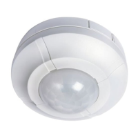
• The adjustment knobs located beneath the sensor head
(see diagram “D”) are factory set to “Walk Test Mode”.
Double check they are set as follows;
TIME – Fully anti-clockwise.
DUSK – Fully clockwise.
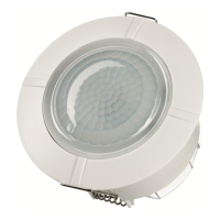
• Push back the locating springs (See diagram “G”) and feed the unit into
the ceiling void via the 75mm hole. The locating springs will now fold
back and hold the SLFM360L in place.
Diagram C Lens Mask Diagram D