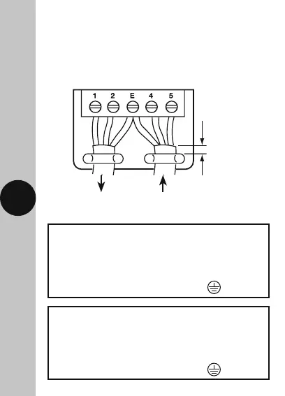
7 8
Supply
Live (Brown or Red) to Terminal 5
Neutral (Blue or Black) to Terminal 4
Earth (Green/Yellow) to Terminal E
Load
Switch Live (Brown or Red) to Terminal 1
Neutral (Blue or Black) to Terminal 2
Earth (Green/Yellow) to Terminal E
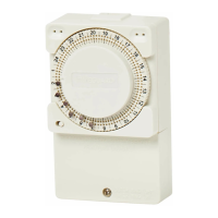
5. Connection Diagram
The terminals are marked as follows on the bottom
of the wall plate;
5mm
minimum
To Heater From Supply
SL N N L