Web: www.tinker-rasor.com E-mail: Info@tinker-rasor.com
107-108
– 7 –
CORROSION MITIGATION INSTRUMENTATION
P. O. BOX 1667 SAN BERNARDINO, CA 92402 TEL: (909) 890-0700 FAX: (909) 890-0736
PRODUCT INSTRUCTIONS
MODEL SR-2 SOIL RESISTIVITY METER
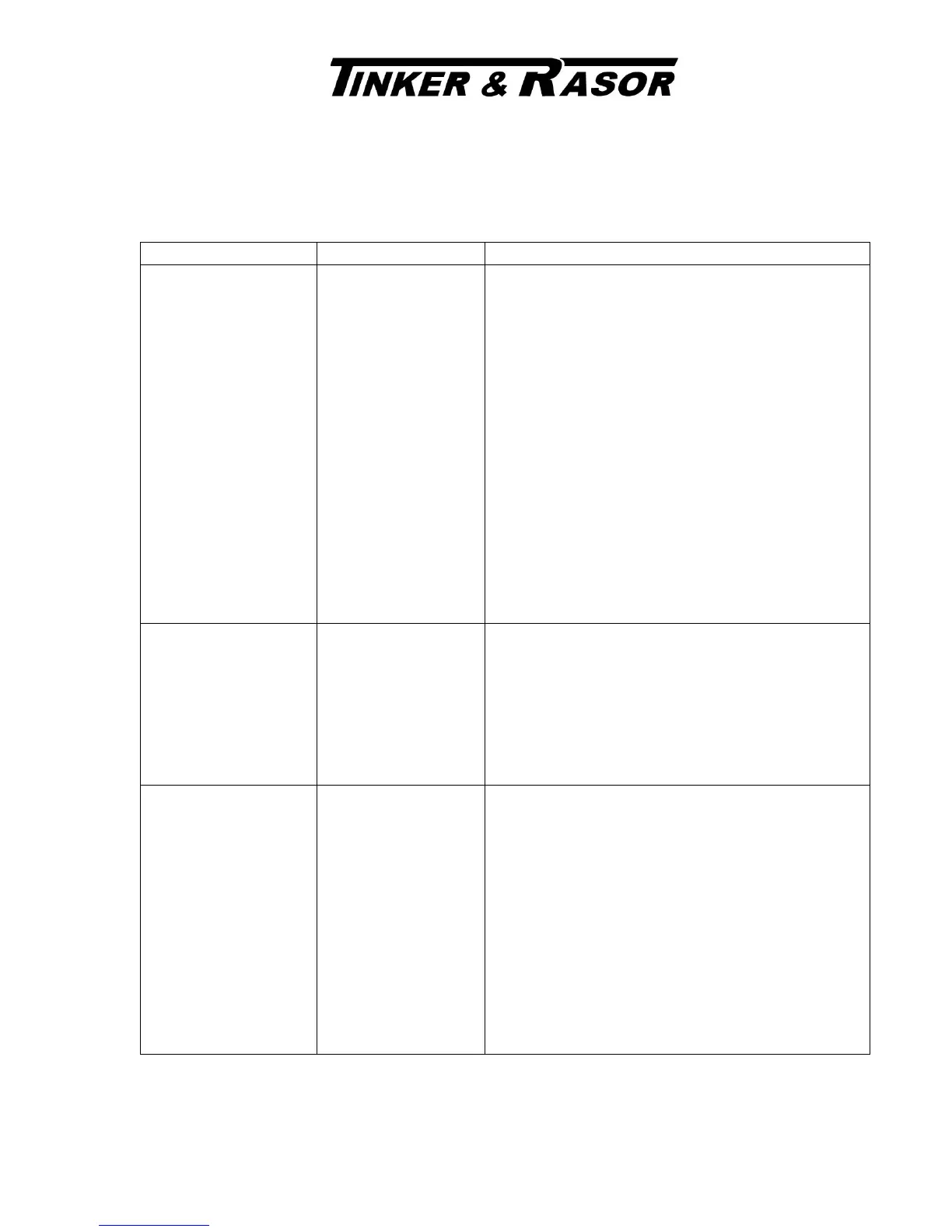
LCD Meter shows
“0000” or a negative
number “-1234”
P1 or P2 connection
error is the most likely
cause.
Another possible cause
is a condition where the
top soil is very dry, and
the underlying soil is
very wet.
Remove the cable for P1 from the instrument panel. LCD
display reading should change.
If no change, P1 has a bad connection to the soil.
If the reading did change, remove the P2 cable from the
instrument panel. LCD display reading should change.
If no change, P2 has a bad connection to the soil.
If the reading does not change, reset pin P1 in the ground
and repeat test. If no change, reset P2 and repeat test.
If no change, check connections between cable and pin,
and cable on SR-2 for faults.
If still no change, try moving all pins to a different line
along the survey path. Perhaps moving only three or four
inches one way or the other.
Adding water around where the pins enter the soil might
be useful as well.
LCD Meter shows 1_ _
_. at each position of the
RANGE SELECTOR
switch
Soil resistance is out of
range of SR-2. (Above
3 MOhm resistance)
Move 2 PIN, 4 PIN METHOD switch to 2 PIN. If the
LCD display shows 1_ _ _. At all ranges, the connection
for C1 or C2 is bad.
Check C1 and C2 as described for P1 and P2 above.
If no connection problems, the resistance is out of range
(> 10 MOhm on 2 PIN, >3 MOhm on 4 PIN)
LCD meter does not
come on when PUSH
TEST button is pushed.
9volt battery needs to
be replaced.
Locate the two black screws on the side of the instrument
case. There is one screw on the left and one on the right of
the case, just below the panel.
Unscrew and remove each screw.
Lift panel up and out of case.
There may be some resistance, as the overlay adhesive has
a bond with the case around the edge.
This should not occur within the first year of operation. If
it does, we recommend sending the instrument in to our
repair department.
DIAGRAM 1 (WENNER 4 PIN METHOD):
 Loading...