• Take a small rubber mallet, and then, while holding the needle bar (CAR-56) in,
tap the needle bar shaft towards the front of the machine. NOTE: You May Have To
Take The Rubber Mallet And Tap The Back Towards The Needle Bar.
• Next, with a punch, 5/32 or larger, apply to back of needle bar shaft
(AR-44).
• Tap the needle bar shaft
(AR-44) until it is flush or slightly recessed with the casting.
• Now, your
(AR 10) gear should pop off.
• Loosen the screw
(SM100-3) that holds the keeper rack (HS-09). NOTE:
THE RACK KEEPER WILL SWING OUT OF THE WAY.
• Remove the rack assembly
(CAR-08)
• After you have received your new rack assembly
(CAR-08):
- Make sure that the 2 pieces of the rack assembly
(CAR-08) are offset as
shown below
.
- If they are not offset, loosen the screw
(AR 100-2), slide halves offset and
tighten the screw
. (Note: If they are offset, there is no need to loosen the
screw.)
• Install new rack gear
(CAR-08)
• NOTE: ALLEN HEAD
SHOULD BE FACING YOU.
• Make Sure that the tip of the rack gear
(CAR-08) is touching the flat washer ,
and hold in place.
• While holding the rack gear
(CAR-08) in place.
- Make sure that the tip of the long ear on the driver shuttle
(AR-42) is at 12:00 .
- If the long ear is not at 12:00 pull the rack gear
(CAR-08) out toward you.
- With the other hand, rotate the driver
(AR-42) to get the tip around 12:00 .
-Then shove gear
(CAR-08) back in.
• Next, tighten the rack keeper screw
(SM100-3).
• Reinstall gear needle shaft
(AR-10)
- Count up to 13 slots
on gear rack (CAR-08) from
where to the 2 pieces join together.
NOTE: This will be the 12th tooth and the 13th slot
.
• Take the gear
(AR-10)
- Go to the 13th slot
on the gear rack (CAR-08)
- Hold the gear
(AR-10) on left side of (AR-10) gear.
- Make sure the gear
(AR-10) is all of the way up.
• Take a rubber mallet and line up gear
(AR-10) with the hole in the
casting and then tap the needle shaft
(AR-44) , while making sure
that the knuckle
(CAR-28) and the knuckle (CAR-27) are lined up.
• Take Bolt
(HS 100-3) and line it back up with (AR-10) and the
hole in the needle shaft
(AR-44).
• Screw bolt
(HS 100-3) back in.
• REPLACE FRONT COVER PARTS:
• Put the pressor foot lifting arm (CAR-24) back on.
• Reattach spring
(HS-39).
• Replace cam driver
(CAR-29) by first putting spring (HS-37) over hook on
knuckle
(CAR-27)
• Then, put spring on pin on
(CAR-29) .
• Next, put the cam driver
(CAR-29) over the pin (CAR-28).
• You will then replace the
CAM (AR-26).
• Replace the snap ring
(HS-47)
• Replace front cover
(AR-30) and 4 front cover bolts / / / (SM-160-3).
• Replace handle
(HS-31) and the handle bolt (100-3).
• Replace back cover
(HS-16) and reassembly is complete.
Call Tippmann’s Toll Free service line 866-286-8046 for further assistance if needed.
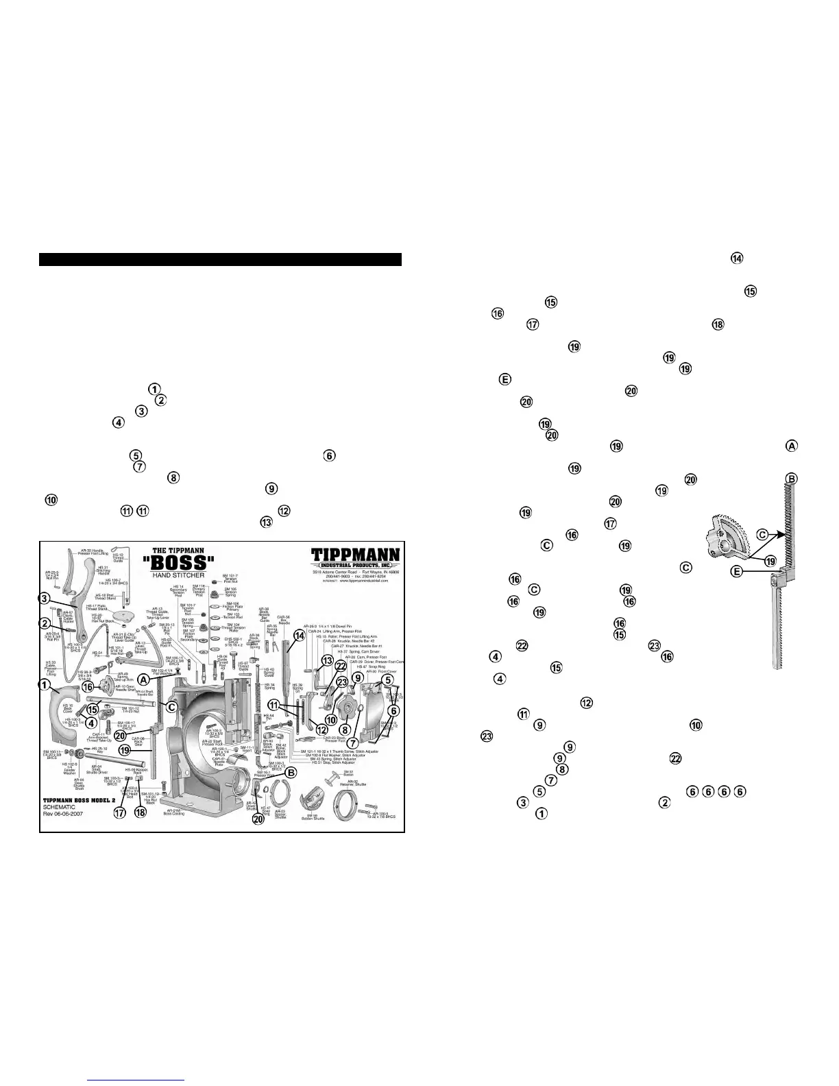
BEFORE DOING ANY MAINTENANCE OR ADJUSTING OF YOUR BOSS HAND
STICHER, MAKE SURE THAT YOUR MACHINE IS MOUNTED ON A STURDY
WORK SURFACE. The following instructions are illustrated in the trouble shooting
section of your instructional and trouble shooting video, which was provided with
your machine. The schematic illustration below has callout numbers to help you
locate the parts quickly, and part numbers to refer to the larger schematic on pages
10 and 11 as necessary. While the schematic below shows the machine in a fully
disassembled view,
it is not necessary to disassemble the machine any more than
specified in the following instructions.
REPLACING THE GEAR RACK:
• Clamp your machine down to the table or work bench.
• Pop off the back cover
(HS-16).
• Remove the handle bolt
(100-3).
• Remove the handle
(HS-31); (You May Have To Tap With A Rubber Mallet.)
• Take gear bolt
(HS100-3) off.
• Turn machine around so that you are facing the machine front.
• Clamp the machine down to the work bench.
• Go the front cover
(AR-30) and remove 4 front cover bolts (SM-160-3).
• Remove snap ring
(HS-47) with snap ring pliers.
• Remove cam presser feet
(AR-26).
• You will then remove the drive presser foot cam
(CAR-29).NOTE: SPRING
(HS-37) WILL COME OFF.
• Remove springs
/ (HS-39) off of the lifting arm (CAR-24).
• You will then remove the lifting arm presser foot
(CAR-24).
16
17
RACK GEAR INSTALLATION & TIMING ADJUSTMENT