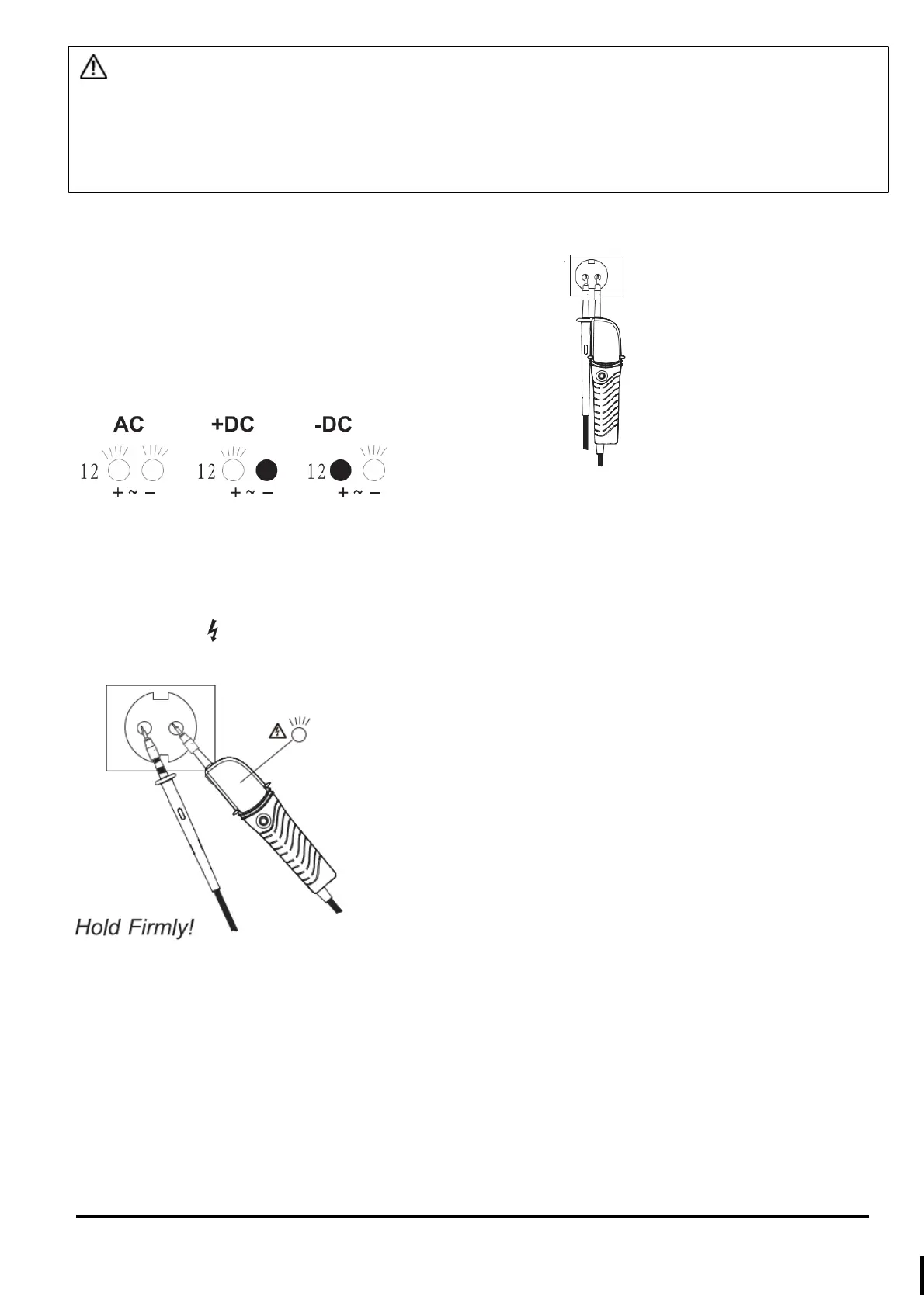
1. Voltage test (Double-pole test)
► Connect both probes to the object under test.
► The voltage is indicated by LEDs and LCD(only TIS 851 ).
Live circuit LED lights up: ≥ 7V
► Voltage polarity is indicated in following manner.
NOTE
• When the L2 probe + is the positive (negative) potential, the Polarity indication LED indicates “+DC” (“-DC”).
2. High voltage indication
► Hold the instrument firmly and connect both probes to the object under test.
► Live circuit LED lights up when a voltage of approx. 50V AC or more exists in the object under test.(Pol> 50V
AC)
3. Phase rotation test
L LED and R LED for Phase roation test may operate on various wiring systems, but an effective testing result can
be obtained only on Three phase system.
► Hold the instrument firmly and connect both probes to the object under test. (hold method shown as below fig)
► Phase-to-phase voltage is indicated by each Voltage LED.
► R LED indicates that the field is rotating towards the right direction of the “probe -”. With this connection, the
motor will go positive rotation.
WARNING
•
Carefully check Clause 2 as well.
•
Self- proving test should be done prior to measurements and confirm LED and buzzer works properly.
•
Before using a voltage detector with audible indicator at locations with a high background noise level, it has
determined whether the audible signal is perceptible.
•
Verify proper operation on a known source before and after use.
•
Keep your hand and fingers behind the barriers on the probes during measurements.