7/21
10
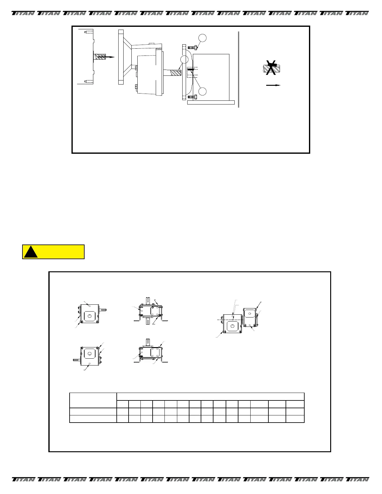
2. VENTILATION - During normal operation gear reducers build up heat and pressure that MUST be vented to protect
the seals and gears. If not installed at Titan, a brass vent plug contained in a small plastic bag, will be put in a box
or larger bag along with fasteners sent loose for use during eld installation. Remove thetop most drain plug (refer
to FIGURE 6 for the position of your reducer) and install the vent plug securely in place.
3. CLEANING - After approximately two to three weeks of operation the reducer MUST be drained, ushed out, and
relled to the proper level with fresh oil. (This is done to remove brass particles caused during thenormal wear-in
period of the worm gear.) Afterwards, the oil should be changed in your reducer every 2500 hours or every
6 months, which ever occurs rst.
Where high temperatures and/or dirty atmosphere exists more frequent changes
may be necessary. Periodically check reducer to ensure that the proper level of
oil is in the reducer. Too little oil will cause accelerated wear on the gears. Too
much oil can cause overheating, seal deterioration, and leakage.
FIGURE 5
SIDEMILL
MOTOR
SHAFT
BORE
REDUCER
KEYSEAT
CUT
MOTOR
SHAFT
1
3
NO!
IF MOTOR SHAFT HAS A KEYSEAT MADE BY AN ENDMILL NO SPECIAL ASSEMBLY STEPS ARE REQUIRED.
THE CORRECT ASSEMBLY PROCEDURE IS TO PLACE THE KEY INTO THE REDUCER KEYWAY.
THEN LINE UP MOTOR KEYSEAT WITH KEY IN REDUCER. PUSH MOTOR SHAFT ONTO REDUCER
AND BOLT TOGETHER.
MANY OF TODAY'S MOTORS HAVE KEYSEATS
CUT WITH A SIDEMILL CUTTER. IF YOU
PLACE THE KEY IN THE MOTOR KEYSEAT
IT CAN SLIDE BACK AS THE MOTOR SHAF
T
IS PUSHED INTO THE HOLLOW INPUT SHAFT
OF THE REDUCER. THIS CAN CAUSE THE
HOLLOW INPUT SHAFT TO BREAKOUT
RUINING THE SEALS, ALLOWING OIL LEAKAGE,
AND FURTHER DAMAGE.
NOTE: IT IS ALSO ADVISABLE TO APPLY FEL-PRO C5A ANTISEIZE OR MOBILETEMP 78 GREASE TO THE
BORE OF THE REDUCER THIS WILL MAKE ANY FUTURE DISASSEMBLY MUCH EASIER..
2
RATIO
MULTIPIER
Mounting
Position
UNIT SIZE
813 815 818 821 824 826 830 832 842 852 860 870* 880* 8100*
1 - Worm Over 4 12 12 20 24 40 56 72 112 188 312 35 48 72
2 - Worm Under 8 16 20 28 40 60 84 108 152 304 328 32-3/4 51-1/4 80
Oil Capacities (ounces) - Standard Units
16 0z. = 1 pint
2 pints = 1 quart
4 quarts = 1 gallon
1 gallon = 128 oz. = 231 Cu. in.
DRAIN
LEVEL
VENT
WORM OVER
VENT
LEVEL
DRAIN
VERTICAL OUTPUT
VENT
LEVEL
DRAIN
WORM UNDER
VENT
LEVEL
DRAIN
VERTICAL INPUT
LEVEL*
VENT
DRAIN
VENT
LEVEL
DRAIN
DOUBLE REDUCTION WORM-WORM
(All primary units have
their own oil level)
* Size 842-860 (far side plug)
Note: High oil level applies to all size 842 & larger
secondary & tertiary units regardless of primary
unit type.
Standard Gear Reducer Mounting Positions
& Vent Plug, Level and Drain Locations
FIGURE 6
 Loading...