Page 21@)1&/2:(+.:4=&A02'/.)+'B&6=24'2&:4==&CD###DE#FDFEC#,Item 57863 57864
GH@<IJKHLMI<MHMN< OHGLN&P<QRLMSP<QRLMS&ILTG G<IUT
1. Press (and hold) Trigger and contact the area
to be welded with electrode wire to ignite arc.
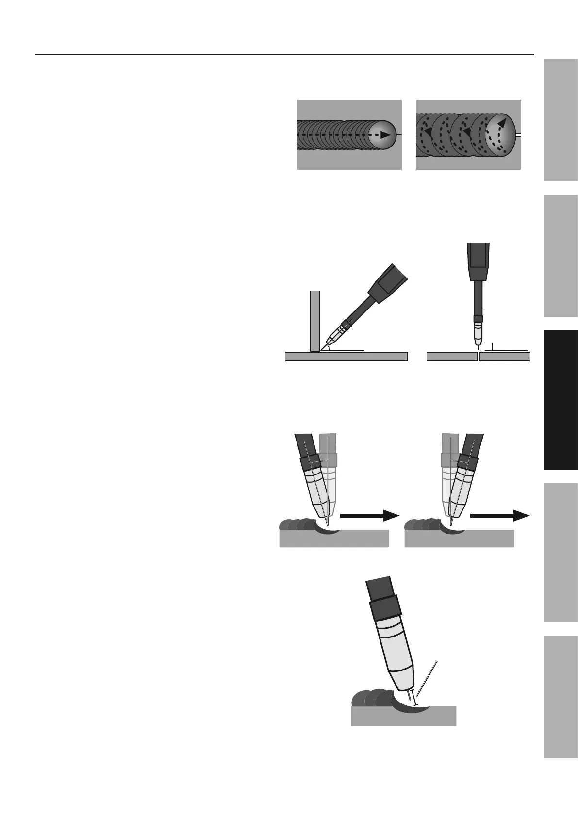
2. For a narrow weld, you can usually draw the wire in
a steady straight line.
This is called a stringer bead.
For a wider weld, draw the wire back and forth
across the joint.
This is called a weave bead and takes
practice to perform properly.
3. Direct the welding wire straight into the joint. This
gives an angle of 90° (straight up and down)
for butt (end to end) welds, and an angle
of 45° for fillet (T-shaped) welds.
4. For MIG welding using solid wire and
shielding gas, the end of the MIG Gun
should be tilted so that wire is angled
anywhere in-between straight on and
15° away from the direction you are welding.
The amount of tilt is called the push angle.
5. When using flux-cored wire without
shielding gas, the end of the MIG Gun
should be tilted so that wire is angled
anywhere in-between straight on and
15° in the direction you are welding.
The amount of tilt is called the drag angle.
6. The Contact Tip should remain within 1/2″
of the work surface. This distance is called
CTWD - Contact Tip to Work Distance.
'/1.+921&324> *24Y2&324>
P2=>&KLS&S0+&4+9=2'B&&
Y.2*2>&81);&81)+/&)8&*2=>&_).+/,
%!k
8.==2/&*2=>&_).+/
90°
30//&*2=>&_).+/
NIPR&&
(up to 1/2")
P2=>&
R.12:/.)+
T0'(&H+9=2T0'(&H+9=2
FDC!kFDC!k
P2=>&
R.12:/.)+
R149&H+9=2R149&H+9=2
FDC!kFDC!k
G)=.>&P.12&*./(&G(.2=>.+9&S4' @=0\DN)12>&P.12&*./()0/&S4'
O4'.:&P2=>.+9&I2:(+.A02