INSTALLATION & WORKPIECE SET-UP3.
SCOPE OF DELIVERY
1. Easytherm 1 / 2 / 3.5 / 15 / 30
2. Yoke(s)
3. Magnetic temperature sensor
4. Support rails
5. Heat-resistant gloves
6. User Manual
INSTALLATION
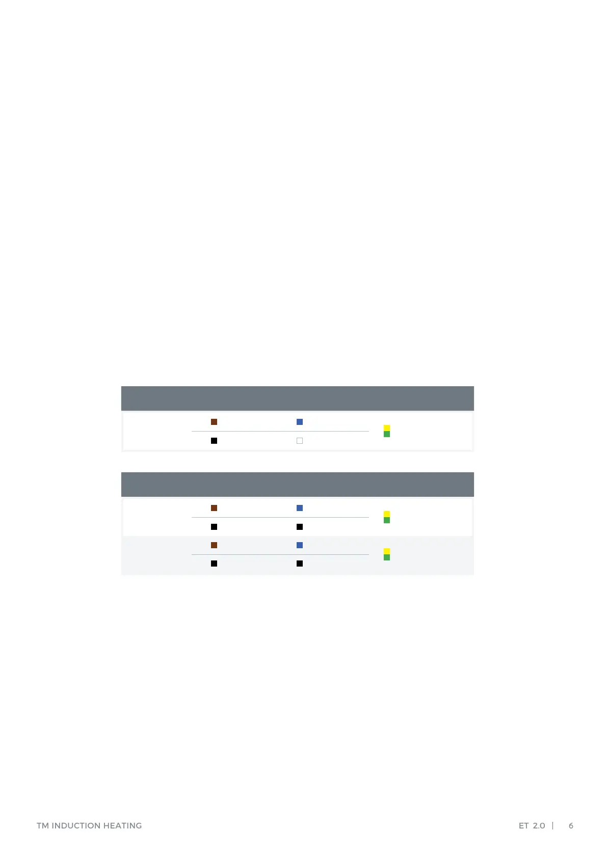
Phase Neutral
Ground
Voltage
BlueBrown
White (USA)Black (USA)
110-230V
Green/Yellow
Phase X / L1
Phase Y / L2
Ground
Voltage
Black (USA) Black (USA)
Brown Blue
400-440V
Green/Yellow
Black (USA) Black (USA)
Brown Blue
460-575V
Green/Yellow
Remove all packing material and place the induction heater on a non-ferrous, stable, at
surface. Ensure that supply voltage, current and mains frequency meet the specications.
These can be found on the type plate at the back of the induction heater.
Each induction heater is provided with a plug, but there are a large number of plug
types. Should the plug not t your power supply, a suitable plug must be axed by a qualied
electrician. Voltages may dier for customized heaters.
Insert the plug into a shockproof wall socket and then connect the heater to mains electricity.
Turn main switch from 0 to 1. The LED display will light up and the induction heater is now
ready for use.