Do you have a question about the Toa 900 II Series and is the answer not in the manual?
Lists key features of the mixer preamplifier, including channels, frequency response, and controls.
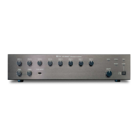
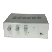
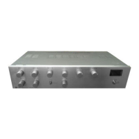
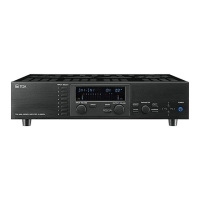
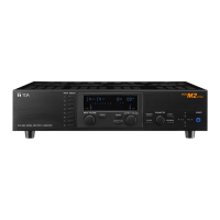
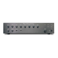
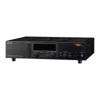
Describes the function of each control and indicator on the front panel of the M-900MK2.
Adjusts the gain for each of the eight input channels on the front panel.
Modifies bass/treble response; tone flat at center. Switch activates/deactivates tone controls.
Adjusts the overall gain of the unit.
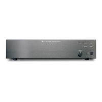
Details the AC power, output terminals, module input ports, and other connections on the rear.
Describes the AC power input and an unswitched AC outlet for auxiliary equipment.
Connects to power amplifiers, specifying 150/600 ohm loads.
Accepts optional plug-in modules for expanded functionality and versatility.
AUX Out for recorders; Bridging I/O for mixing bus or recording output.
Terminals for remote volume control and muting functions.
Instructions on how to plug in and secure optional modules into the input ports.
Details connecting power amplifiers to 600-ohm or 150-ohm output terminals.
Explains how to use an RCA phone jack with shielded cable for AUX output.
Diagram and explanation for connecting muting and remote volume control functions.
Instructions for mounting the amplifier in a standard 19" equipment rack using an optional bracket.
Recommendations for ventilation and perforated panels when rack mounting multiple units.
Steps for turning on the power and initial amplifier operation.
How to adjust input and master volume controls for desired output levels.
How to use the tone controls and tone defeat switch for frequency response adjustments.
Warnings about placement, ventilation, sunlight, humidity, temperature, and vibration.
Caution against removing the cover to avoid risk of electrical shock.
Procedures for inspecting the unit for transit damage and reporting issues.
Guidance on what to do in case of amplifier failure and whom to contact.
Comprehensive list of technical specifications including type, output, frequency response, distortion, and inputs/outputs.
Lists the number and type of controls, switches, and indicators on the unit.
Details protection features like self-protection and AC fuse, and lists connector types.
Provides power consumption, operating temperature, dimensions, weight, color, and standard accessories.
Shows the front panel layout with dimensions and labels for inputs and controls.
Illustrates the rear panel connections and ports.
Provides top and side views of the unit, including dimensions.