Do you have a question about the Toa Venas VM-2240 and is the answer not in the manual?
Describes the RM-200M remote microphone and its use for general purpose and emergency broadcasts.
Describes the RM-210 extension unit for controlling key system operations.
Discusses combining VM-2000 series amplifiers for expanded coverage and using SV-200M for system integrity monitoring.
Details EV-200 capabilities for messages/chimes and VM-2000's emergency broadcast features per EN60849.
Covers speaker line distribution options and the system's capacity for remote microphones (RM-200M).
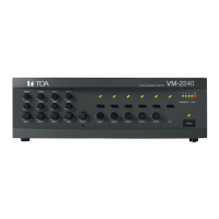
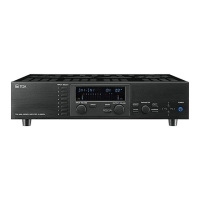
Identifies and explains the controls and indicators on the front panel of the VM amplifier.
Details the various input/output jacks and connectors on the rear panel of the VM amplifier.
Explains the components and indicators of the EV-200 Voice Announcement Board.
Describes the SV-200M Surveillance Board and its connectors.
Details the top, right side, and rear panel components of the RM-200M remote microphone.
Illustrates the top and left side components of the RM-210 Remote Microphone Extension.
Explains how to set input levels (Mic/Line) and details usable connectors for Inputs 1-3.
Details the functions assigned to the SETTINGS switches for Inputs 1-3.
Describes the two BGM inputs, their specifications, and connectable equipment.
Illustrates how to connect a cassette player and CD player to the BGM inputs.
Explains how to connect the VM amplifier to a telephone exchange for remote paging.
Shows the location of the telephone paging volume control and connection details.
Details how to use the VS-900 with the VM amplifier for station-based broadcasts to set zone groups.
Provides an example of configuring VM amplifier group settings and VS-900 control signals for zone broadcasts.
Explains how to connect a timer (TT-104B) to broadcast a chime tone at preset times.
Details connecting a timer to the EV-200 for preset playback of recorded memory card messages.
Lists and describes the functions of each pin on the VM amplifier's D-sub female control I/O connector.
Provides detailed explanations for specific control I/O pin functions like power control and emergency alerts.
Lists control and audio functions that can be operated using the RM-200M/RM-210 remote microphones.
Outlines the status indicators that can be confirmed on the RM-200M remote microphone.
Explains how to perform simultaneous all-zone, individual zone, and group broadcasts using the remote microphone.
Details the press-to-talk and lock operation modes of the remote microphone's TALK key.
Describes how to broadcast prerecorded messages using the MESSAGE key on the remote microphone.
Shows two connection patterns for linking multiple RM-200M units to the VM amplifier system.
Illustrates link cable connections and specifies the maximum total cable length for remote microphones.
Explains how the VM amplifier supplies power to one remote microphone and the need for separate power for others.
Lists available optional AC adaptors for powering remote microphones.
Describes a system modification to eliminate AC adapters for the first RM-200M connected to VM amplifiers.
Introduces the EV-200 as a digital sound source playback card for automatic and emergency broadcasts.
Explains the EV-200's surveillance function for monitoring its operating status and detecting failures.
Details how to activate prerecorded messages on the CF card using the VM amplifier's control I/O terminal.
Lists the specific pin numbers on the control I/O connector for activating each of the five messages.
Categorizes messages (1-5 general, 6-7 emergency, 8 chime) and their intended use with the EV-200.
Provides an example table showing message numbers, playback methods, sentence numbers, and remarks.
Explains the process of prerecording messages on a CompactFlash card using the EV-350R.
Explains the priority system for emergency and general-purpose broadcasts in the VM-2000 series.
Details how various broadcast sources are assigned priority levels and their functional explanation.
Shows how to use DIP switches (SW2) on the VM amplifier to set priority levels for inputs.
Explains priority settings for simultaneous broadcasts at the same level (SW3-1, SW2-8).
Details the functions of SW3 switches for mixing, talk modes, and unit type settings.
Describes expanding the VM amplifier system with sub-amplifiers, zones, and remote controls.
Illustrates the connection of multiple RM-200M, RM-210, and EV-200 units to a master VM amplifier.
Explains settings required for connecting 3 or more VM amplifiers, including master-sub relationship and unit numbers.
Details how to set unit numbers for sub-amplifiers using jumper headers on the CPU circuit board.
Shows two patterns for connecting speakers to the VM amplifier's 5 zones, up to its maximum output.
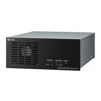
Explains how to connect external PA amplifiers to the VM amplifier's speaker outputs to increase total output.
Details the 1/100 attenuator circuit used for connecting external amplifiers to VM speaker outputs.
Explains the quasi-dual-origination broadcast feature when the VM amplifier is connected to a BGM amplifier.
Describes the connection and internal operation settings for performing quasi-dual-origination broadcasts.
Explains how to set up a backup system for VM amplifier failure using a standby amplifier.
Details connecting a standby amplifier and its failure detection output to the VM amplifier system.
Explains a system enabling both standby and quasi-dual-origination broadcast functions using the same amplifier.
Details the system connection for utilizing both BGM amplifier for quasi-dual broadcasts and standby amplifier.
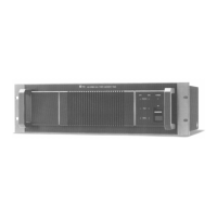
Describes how to mount the VM amplifier in a standard EIA rack using optional MB-36 hardware.
Explains connecting a condenser microphone with a 3.5mm mini-jack to the RM-200M's external microphone input.
Details how VM-2000 series amplifiers conform to EN60849 standards for emergency broadcast systems.
Outlines general system requirements for emergency broadcasts, such as response time and functionality.
Highlights features like immediate activation, message recording, and monitoring for emergency broadcasts.
Shows a system using the VM amplifier for both general-purpose and emergency broadcasts, including fire alarm integration.
Describes three methods to initiate an emergency broadcast: Remote Mic button, Fire Alarm signal, or manual activation.
Illustrates the sequence of events during emergency broadcasts, including activation, alerts, and restoration.
Explains which general-purpose broadcasts are restored and which are not after an emergency broadcast ends.
Describes using the VM amplifier as a local amplifier that switches to an emergency broadcast amplifier for the entire building.
Lists the failure detection capabilities included as standard in VM-2120/VM-2240 amplifiers.
Details the enhanced failure detection functions added by installing the optional SV-200M unit.
Explains the operational principles of the SV-200M's failure detection circuitry, including power amp and speaker line checks.
Describes the process of initial impedance setting and speaker line checks performed by the SV-200M.
Covers limitations on impedance checks during broadcasts and timer settings for checks.
Explains the need for an SV-200M in each amplifier for system-wide surveillance and connecting to an indication board.
Lists the various indicators on the Monitor Display board that show the status of connected amplifiers and components.
Details the pin functions of the SV-200M's Surveillance I/O connector for external monitoring.
Describes the signals for activating speaker line checks and initial setting measurements.
Explains how active low signals from the VM amplifier and SV-200M control the indicator LEDs on a custom panel.
Provides schematic diagrams for the master and sub VM amplifier's control and surveillance I/O connections.
Presents a comprehensive block diagram of the VM amplifier system, showing inputs, processing, and outputs.
Details the technical specifications for the VM-2120 and VM-2240 System Management Amplifiers.
Lists the technical specifications for the RM-200M Remote Microphone.
Provides the technical specifications for the RM-210 Remote Microphone Extension Unit.
Details the technical specifications for the EV-200 Voice Announcement Board.
Lists the technical specifications for the SV-200M Surveillance Board.