Do you have a question about the Toa Venas VM-2120 and is the answer not in the manual?
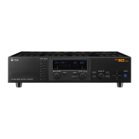
Introduction to the VM-2120/VM-2240 amplifiers for reliable communications in mid-size facilities.
Highlights system expandability, surveillance, remote microphone, and announcement board integration.
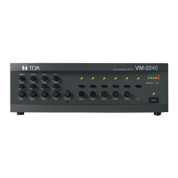
Detailed identification of controls and connectors on the VM-2120/VM-2240 amplifier.
Identification of components for Voice Announcement Board, Surveillance Board, and Remote Microphones.
Setting and connecting Inputs 1-3 for microphone or line level signals using various connector types.
Details on RCA pin jack BGM inputs, including attenuator adjustment for different sound sources.
Connecting a telephone device for remote paging, enabling zone selection and volume control.
Using the VS-900 for station broadcasts and assigning zone groups via control signals.
Using the control I/O terminal to schedule chime tones or prerecorded messages with an external timer.
Detailed pinout and function of the rear panel Control I/O connector for external control and monitoring.
Enabling broadcasts from RM-200M/RM-210, including zone/group broadcasts and emergency activation.
Step-by-step guide for all-zone, individual, and group broadcasts using the RM-200M.
Broadcasting prerecorded messages (1-5) via the MESSAGE key on the remote microphone.
Wiring patterns for connecting multiple RM units to the VM amplifier, including series connection.
Guidelines for connecting remote microphones via LINK connectors, specifying a maximum total cable length of 800m.
How the VM amplifier powers one RM unit; others require separate AC adapters.
Configuring link cables to eliminate AC adapters for the first RM-200M connected to each VM amplifier.
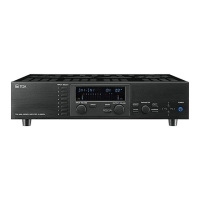
Introduction to the EV-200 for automatic and emergency broadcasts using CF cards.
Activating prerecorded messages on CF cards using the VM amplifier's control I/O terminal.
Details on recording general-purpose, emergency, and chime tone messages on CF cards.
Procedure for prerecording messages on CF cards using the EV-350R for the EV-200.
Overview of priority levels for emergency and general broadcasts, including interruption capabilities.
Configuring input, remote microphone, and announcement board priorities using DIP switches.
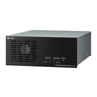
Expanding the system with up to 8 sub-amplifiers to support 45 zones.
Settings for master-sub relationship and unit numbering when connecting 3+ VM amplifiers.
Two patterns for speaker connection to VM amplifiers (5 zones or single zone).
Connecting external PA amplifiers to VM speaker outputs for increased total output power.
Simultaneous BGM and microphone broadcasts where microphone takes precedence over BGM.
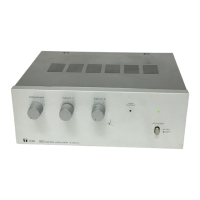
Connecting BGM amplifier speaker output to VM amplifier's external speaker input for dual broadcasts.
Creating a backup system using a standby amplifier and failure detection for VM amplifier redundancy.
Setting up standby amplifier, SV-200M, and failure detection for amplifier failure backup.
System enabling both standby and quasi-dual broadcast functions using BGM and VM amplifiers.
System setup for dual broadcasts and standby operation via relay control.
Instructions for mounting the VM amplifier in an EIA rack using optional MB-36 hardware.
Connecting a 3.5mm mini-jack headset microphone to the RM-200M for hands-free operation.
Overview of emergency broadcast system requirements and VM amplifier compliance with EN60849.
Using the VM amplifier for emergency alerts with fire alarm systems and remote microphone activation.
Flowchart detailing the sequence of emergency broadcasts and restoration to normal operation.
Using the VM amplifier as a local unit that switches to an emergency broadcast amplifier for building-wide alerts.
Failure detection capabilities of VM amplifiers and additional functions provided by the SV-200M unit.
Installing SV-200M in each amplifier for system surveillance and external indication board connection.
Pinout and functions of the Surveillance I/O connector for impedance measurement and line checks.
Illustrates a custom panel connected to VM amplifier I/O for monitoring status LEDs.
Wiring diagrams for control signals and status monitoring connections.
Overall system block diagram showing signal flow, inputs, outputs, and internal components.
Technical data for VM-2120, VM-2240, RM-200M, RM-210, EV-200, and SV-200M units.