SURVEILLANCE FUNCTIONS SURVEILLANCE FUNCTIONS
6-1
SV-200M Functions
The failure detection circuitry included as standard-equipment in the VM-2120 and VM-2240 amplifiers
permits
• Communication error output (the number of connected units needs to be set)
• Failure detection by way of the optional EV-200 unit.
By installing an optional SV-200M unit, the following failure detection functions can be added.
• Failure detection of output zones 1 - 5
Detection of shorted or opened circuits for individual lines + simultaneous detection of ground faults of 5 zones.
• Power amplifier failure detection.
When any of these failures is detected, a common failure output is generated in addition to an individual
failure output. The failure indicator LEDs on the VM amplifier front panel and the Remote Microphone are
also illuminated.
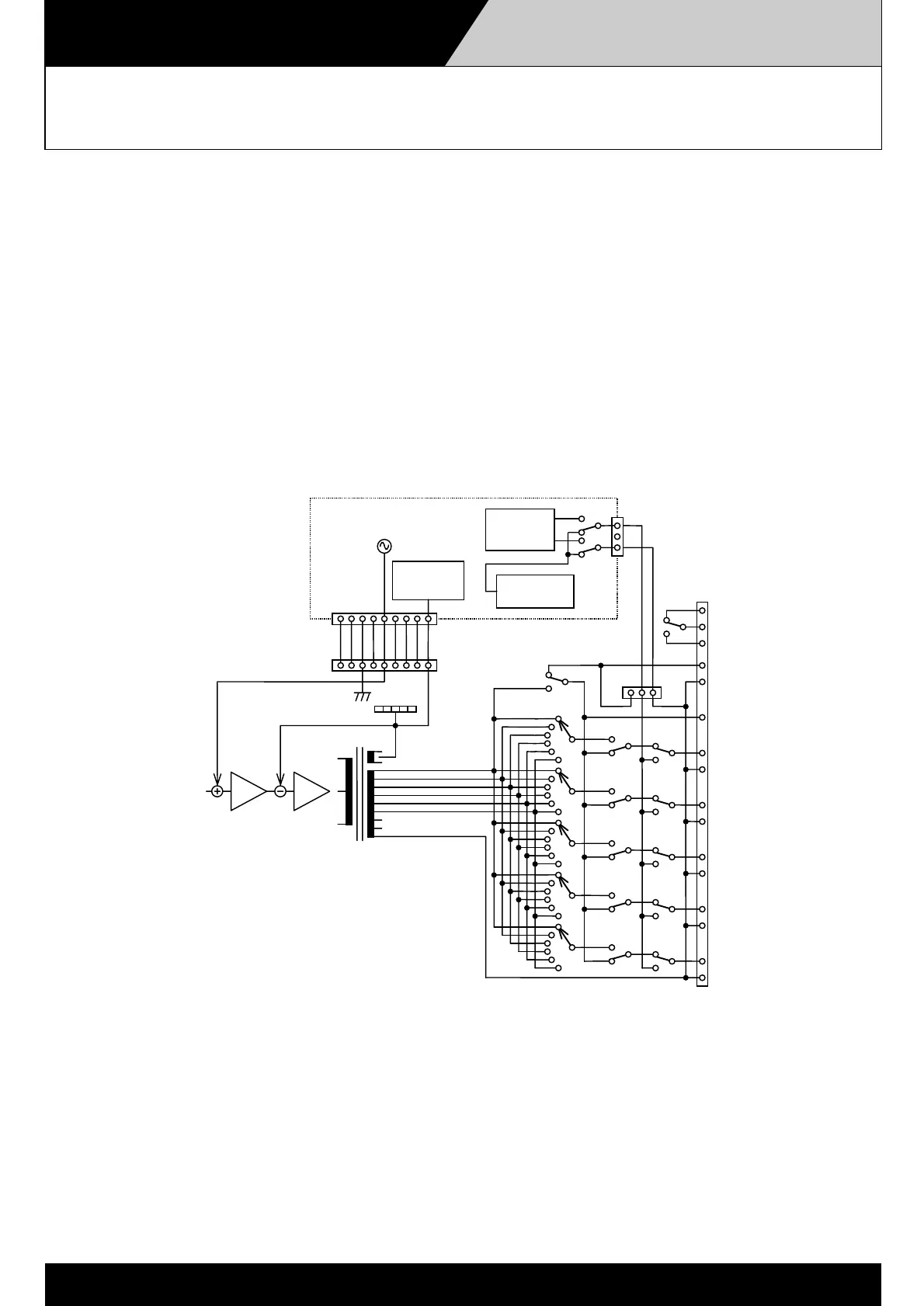
Failure detection circuit operation
The power amplifier failure is determined by superimposing a 20 kHz pilot signal over the audio signal at the
power amplifier input and monitoring the power amplifier output for the pilot signal. This failure detection is
constantly enabled.
Speaker line ground failure is detected by monitoring all speaker lines after the power amplifier's output
transformer secondary side in a group. Failures are assumed if the impedance at ground falls to under 50 kΩ.
This detection is constantly enabled.
An impedance measuring method employing a 40 Hz pilot signal is used to detect the short- or open- circuit
failures. Initially, each speaker line impedance is measured and its reading stored (initial setting). When the
speaker line check is activated, the speaker line impedance is compared with the initial reading and failure is
determined by impedance deviation.
1
OT
1
H
C
H
H
C
H
C
H
C
H
C
H
C
N1
C
N2
1
1
SV-200M
Impedance
Detector
Grand fault
Detector
Pilot tone
Detector
Pilot tone
Generator
CN1
CN2
CN6
Power Amp.
CN1003
Zone vol.
SV-200M Block Diagram
 Loading...