GENERAL PURPOSE BROADCAST INPUT
External Connection Terminal
(VS-900)
4-1-4
RS-150
VS-900
Control 1
Zone 1
Zone 2
Zone 3
Zone 4
Zone 5
RS-160
RS-170
RS-180
RS-180
Control 2
Audio
CTRL IN 1
CTRL IN 2
INPUT 2
INPUT 1
VM amplifier
ZONE-1
ZONE-2
ZONE-3
ZONE-4
ZONE-5
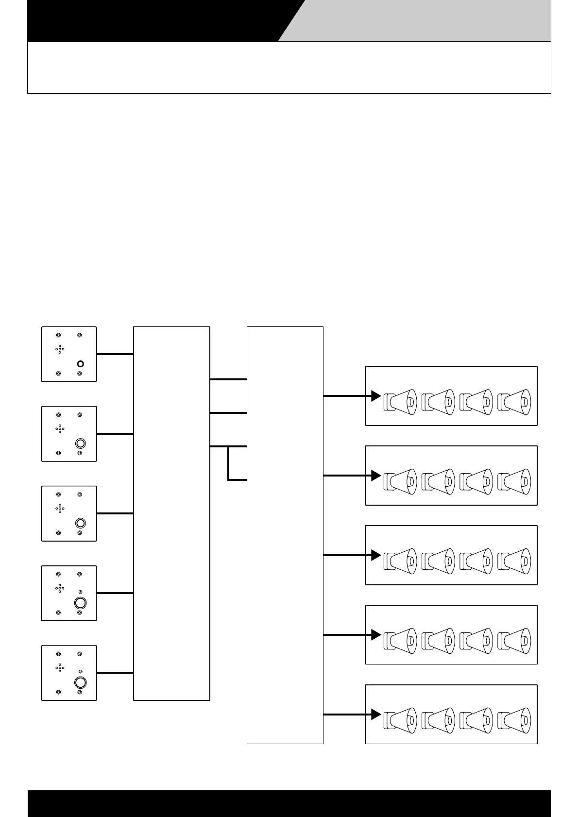
Use of the VS-900 in conjunction with the VM amplifier permits broadcasts to be made from each station
connected to the VS-900. Configure the connections so that two control signals are transmitted from the
VS-900 to the VM amplifier's CTRL IN 1 and CTRL IN 2 terminals, then assign different zone groups to
the two terminals. This enables each station to make broadcasts to the set zone group.
Example
In the VM amplifier group settings, assign Zones 1, 2, and 3 to Group 1, and Zones 4 and 5 to Group 2. Set the
VS-900 to output an activation signal from CONTROL 1 when broadcasts are made from the RS-150, and to
output an activation signal from CONTROL 2 when broadcasts are made from the RS-160. By setting the
VM amplifier and VS-900 in this way, broadcasts can be made to Zones 1, 2, and 3 from the RS-150, and to
Zones 4 and 5 from the RS-160.
 Loading...