Do you have a question about the Toa M-900MK2 and is the answer not in the manual?
Lists key features like 8-channel mixing, wide frequency response, low distortion, and module compatibility.
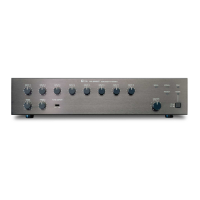
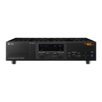
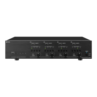
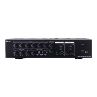
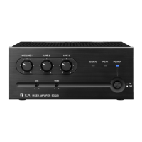
Identifies and explains the function of all buttons, knobs, and LEDs on the front panel.
Details the various input/output terminals, AC outlet, and module ports on the rear panel.
Describes the procedure for inserting plug-in modules into the eight input ports.
Explains the 600-ohm and 150-ohm output connections for amplifiers and the AUX Out.
Details how to connect for muting functions and remote master volume control.
Explains how to mount the unit in a 19" equipment rack using optional brackets.
Covers powering on, volume adjustment, and tone control settings for normal use.
Advises on suitable environments and critical safety warnings regarding electric shock.
Guides on inspecting for shipping damage and contacting service for failures.
Lists detailed technical data including type, output, frequency response, THD, and input/output impedance.
Details the unit's controls, indicators, protection, connectors, power consumption, and temperature range.
Presents front, rear, top, and side views with key dimensions for physical reference.
| Finish | Black |
|---|---|
| Type | Mixer Amplifier |
| Power Source | AC 120 V, 60 Hz |
| Total Harmonic Distortion | 0.5% or less |
| Total Harmonic Distortion (1kHz, rated output) | 0.1% |
| Signal-to-Noise Ratio | 100dB or more |
| Signal-to-Noise Ratio (A-weighted) | 100dB or more |
| S/N Ratio | 100dB or more |
| Input Impedance | Mic: 600Ω, Line: 10kΩ |
| Tone Control | Bass: ±10dB at 100Hz, Treble: ±10dB at 10kHz |
| Operating Temperature | -10°C to +40°C |
| Cooling | Natural air cooling |
| Protection | Overcurrent protection, Thermal protection |