Do you have a question about the Toa FV-200 Series and is the answer not in the manual?
Explains safety symbols and messages to prevent injury and property damage.
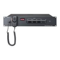
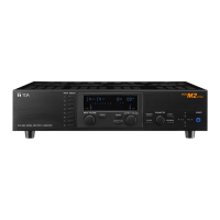
Emergency broadcast operation panel for FV-200 Series. Manual operation of alerts.
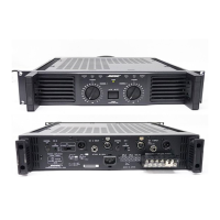
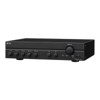
Standard operation panel with pre-amplifier. 2-channel or 1-channel output.
Connects RM-200M to FV-200 Series. Controls 50 speaker lines and all-zone calls.
Automatically changes over duty amplifier to standby. Handles up to six duty amplifiers.
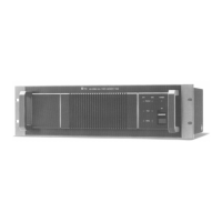
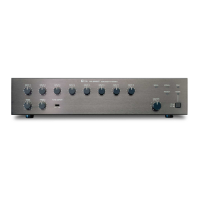
240W power amplifier panel. Features indicators for fault, peak, signal, and power.
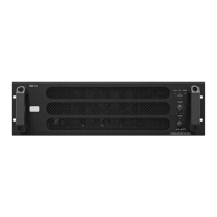
480W power amplifier panel. Indicators for fault, peak, signal, and power.
Unidirectional microphone for zone broadcasting. Features zone selection and talk keys.
Expansion unit for RM-200M. Expands zone selection keys up to 10 per unit.
Module for power amplifier input slot. Connects to SX-2100AO or VX-2000 series.
Supplies 24 V DC to FV-200 series units. Connects to emergency power supply.
Instructions for mounting panels in a cabinet rack and ensuring proper clearance.
Example of rack cabinet layout, showing placement of various FV-200 series units.
Instructions for wall mounting the RM-200M using the WB-RM200 bracket.
Instructions for wall mounting the RM-210 extension unit with the WB-RM200 bracket.
Guide for linking RM-200M and RM-210 units for desktop setup.
Instructions for inserting name labels into the entry slits on RM-200M and RM-210.
Provides cutting dimensions for name labels for RM-200M and RM-210.
Provides pattern paper templates for hand-writing labels.
Step-by-step guide for installing the VP-200VX module into power amplifier rear panels.
Procedure to resolve hum noise by adjusting ground lift jumper on VP-200VX.
Diagram showing the basic system configuration and interconnections of FV-200 series units.
How to expand 24V DC power supply when component current exceeds 5A.
Connects FV-200EV-AS for automatic evacuation guidance with fire alarm systems.
Connects timer-operated equipment to FV-200PP-AS Timer Input for timer broadcasts.
Connects telephone exchange paging trunk to FV-200PP-AS Paging Input for telephone paging.
Connects ALL-CALL and RF-PP LINK terminals between FV-200PP-AS and FV-200RF-AS.
Details connecting multiple RM-200M units to the FV-200RF.
Describes powering RM-200M via FV-200RF-AS and maximum cable distances.
Explains using AD-246 AC adapter for RM-200M power and notes on DC plug insertion.
Connects BGM instruments to FV-200PP-AS MIC/LINE and AUX inputs. Mentions muting function.
Details connections for power amplifiers in broadcast setups.
Connects speakers and attenuators, enabling max volume during emergency broadcasts.
Connects amplifier fault outputs and duty/standby outputs to FV-200CA-AS for changeover.
Shows cascading FV-200CA-AS units for more amplifier connections.
Warns against connecting 100V amplifier output to CA LINK or FAULT IN terminals.
Details connections for speaker selectors like SS-2010 and SS-1010.
Connects FV-224PA-AS and FV-200CA-AS to SS-1010R for 1-channel speaker selection.
Connects FV-200EV-AS to automatic fire alarm system for automatic fire alert announcements.
Connects power amplifier fault out terminals to external equipment for failure notification.
Details UPS requirements for uninterrupted operation during power failures.
Using VX-2000DS for backup power. Mentions storage battery capacity calculation.
Wiring diagram showing connection of FV-200PS-AS to a UPS system.
Wiring diagram showing connection of FV-200 series equipment to VX-2000DS.
Settings for the FV-200RF-AS microphone receiver panel.
Settings for the RM-200M and RM-210 remote microphones.
MIC/LINE input 1 has priority, reducing other input volumes via MUTE ADJ.
Adjusting output levels with volume controls and monitoring peak indicators.
How to conduct emergency broadcasts manually or via fire alarm system. Highest priority.
Classifies general-purpose broadcasts by equipment, priority, and type.
Manual operation for emergency broadcasts using microphone or pre-recorded messages.
How to perform individual zone broadcasts using RM-200M zone selector and talk keys.
Explains the red Error indicator on FV-200RF-AS and possible causes.
Explains the orange Fault indicator on RM-200M and possible causes.
Explains the red Fault indicator on FV-224PA-AS for overheat and other failures.
Explains the red Fault indicator on FV-248PA-AS units for overheat and other failures.
Explains FV-200CA-AS fault indicators and changeover logic for amplifier faults.
Detailed technical specifications for the FV-200EV-AS panel.
Detailed technical specifications for the FV-200PP-AS pre-amplifier mixer panel.
Detailed technical specifications for the FV-200RF-AS microphone receiver panel.
Detailed technical specifications for the FV-200CA-AS amplifier changeover panel.
Detailed technical specifications for the FV-224PA-AS 240W power amplifier.
Detailed technical specifications for FV-248PA-AS 480W power amplifiers.
Detailed technical specifications for the VP-200VX power amplifier input module.
Detailed technical specifications for the RM-200M remote microphone.
Detailed technical specifications for the RM-210 remote microphone extension.
Detailed technical specifications for the FV-200PS-AS DC power supply panel.