Do you have a question about the Toa FV-224PA-AS and is the answer not in the manual?
Explains safety symbols (Warning, Caution) and message conventions used in the manual.
Details safety measures to be taken during unit installation, covering various environmental and physical aspects.
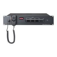
Provides step-by-step instructions and required parts for mounting the RM-200M on a wall.
Guides the user on how to mount the RM-210 unit on a wall, referencing RM-200M installation.
Details the process and parts needed to link RM-200M and RM-210 units for desktop mounting.
Illustrates the overall system wiring diagram, showing connections between various TOA units.
Explains how to expand the 24V DC power supply and lists current consumption of components.
Explains connecting speakers and attenuators, including 24V DC supply for emergency broadcasts.
Illustrates connecting power amplifiers for automatic changeover using the FV-200CA-AS.
Shows how to cascade FV-200CA-AS units for expanded amplifier changeover capability.
Explains how automatic fire alarm systems integrate with the FV-200EV-AS for fire alert announcements.
Outlines requirements for using a UPS to provide backup power for continuous operation during power failures.
Details using the VX-2000DS for emergency power backup, referencing its manual.
Provides a wiring diagram showing how to connect the FV-200PS-AS to a UPS system.
Shows the recommended wiring connection of FV-200 system equipment to the VX-2000DS.
Explains DIP switch functions and priority settings for the FV-200RF-AS.
Covers DIP switch functions for Unit ID, Talk Key, and Compression settings on the RM-200M.
Details how emergency broadcasts are initiated manually or automatically, and their priority.
Outlines the priority order for different types of broadcasts and RM-200M units.
Describes manual and automatic procedures for emergency broadcasts using the FV-200EV-AS.
Guides on selecting zones and making broadcasts using the RM-200M's zone selector and talk key.
Explains how to perform an all-zone broadcast using the ALL-ZONE key on the RM-200M.
Explains the meaning of the red error indicator on the FV-200RF-AS and troubleshooting.
| Operating Temperature | -10 °C to +40 °C |
|---|---|
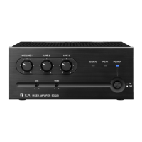
| Type | PA Amplifier |
| Power Source | AC 100V, 50/60Hz |
| Frequency Response | 50 Hz - 20 kHz |
| Total Harmonic Distortion | 1% or less (at 1kHz, rated output) |
| Signal-to-Noise Ratio | More than 60 dB |
| Tone Control | BASS: ±10dB (at 100Hz), TREBLE: ±10dB (at 10kHz) |
| Control | MIC VOLUME, LINE VOLUME, MASTER VOLUME, BASS, TREBLE |
| Indicator | Power LED |
| Finish | Black |
| Input Impedance | 10 kΩ |
| Power Supply | AC 220-240 V |