EasyManuals Logo

Toa H-2 User Manual

Toa H-2
12 pages
To Next Page IconTo Next Page
To Previous Page IconTo Previous Page
Page #8 background imageLoading...
Page #8 background image
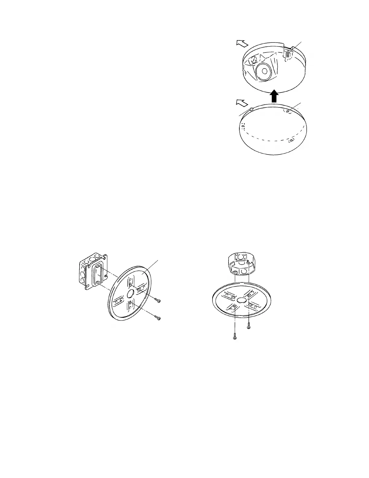
3-4. Set the front grille's aiming marker to the speaker
front (i.e. speaker orientation) so that the three stud
screws align with the corresponding stud receptacles,
then push the grille onto the speaker.
Speaker front
Stud screw
Aiming marker
Stud receptacle
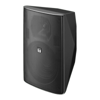
6.2. Mounting the Speaker using a Electrical Box
The speaker system can be mounted to walls or ceilings using a electrical box*. Mount the base frame to the
electrical box using two holes shown in the figure below. Further mounting procedures are the same as
detailed in Steps 2 and 3.
* Distance between mounting holes: 69.9 mm (2 ¾), 83.3 mm (3
9
/32) or 88.9 mm (3 ½ )
Mounting example 1
Base frame
Mounting example 2
Memo
Electrical box mounting screws are attached to the speaker.
8

Questions and Answers:

Question and Answer IconNeed help?

Do you have a question about the Toa H-2 and is the answer not in the manual?

Toa H-2 Specifications

H-2

Power IconPower
power handling continuous program input120 W
power handling continuous pink noise input40 W
rated input12 W
Acoustic Specifications IconAcoustic Specifications
output sound pressure level88 dB
frequency response100 Hz to 20 kHz
crossover frequency5, 000 Hz
Weight and Dimensions IconWeight and Dimensions
dimensions268 x 111 mm
weight2.1 kg

H-2WP

Power IconPower
power handling continuous program input120 W
power handling continuous pink noise input40 W
rated input12 W
Acoustic Specifications IconAcoustic Specifications
output sound pressure level88 dB
frequency response100 Hz to 20 kHz
crossover frequency5, 000 Hz
Weight and Dimensions IconWeight and Dimensions
dimensions268 x 111 mm
weight2.1 kg

Related product manuals