Do you have a question about the TOHATSU MD 70-90C2 and is the answer not in the manual?
Provides guidance on how to use the manual effectively.
Details important safety statements and symbols used in the manual.
Explains the meaning of DANGER, WARNING, and CAUTION statements for hazard identification.
Explains the structure and components of the service manual for efficient repair.
Pictographs representing service categories like information, data, maintenance, troubleshooting, etc.
Pictographs for special tools, specified values, and parts required for service procedures.
Pictographs indicating specific lubricants, sealants, and locking agents for various applications.
Information on locating and identifying the engine serial number on the outboard motor.
Outlines critical safety precautions for handling gasoline, ventilation, personal protective equipment, and genuine parts.
Lists and describes essential tools and measuring instruments required for servicing the outboard motor.
Details the step-by-step inspection procedures required before delivering the outboard motor to the customer.
Explains the purpose and procedure for the initial break-in operation of the outboard motor.
Guides on performing a test run after service to ensure proper operation and identify any issues.
Outlines post-test run checks to verify the condition of the gear oil, fuel, and oil/water leaks.
Provides detailed body and clamp dimensions of the outboard motor for installation and reference.
Illustrates the cooling water flow path through the engine components.
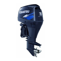
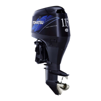
Lists technical specifications for dimensions, weight, performance, and power unit details of the outboard motor.
Provides detailed maintenance specifications including functional limits and recommended actions for engine parts.
Details tightening torque values for various engine components and fasteners to ensure correct assembly.
Specifies recommended sealants and lubricants for different engine parts and their application areas.
Lists warning indicators, buzzers, and their corresponding meanings for diagnosing operational abnormalities.
Lists and illustrates special tools required for performing maintenance procedures.
Provides a schedule for regular inspections of various engine systems based on time or usage intervals.
Details specific items to inspect within different engine systems during scheduled maintenance.
Covers inspection procedures for fuel pipes, tank, filters, pressure, and drive belt in the fuel system.
Outlines inspection procedures for spark plugs, compression pressure, thermostat, and cooling water passages in the power unit.
Details adjustments for throttle and shift cables, and inspection of idle engine speed.
Covers inspection of the Power Trim & Tilt unit operation and fluid quantity.
Details inspection and replacement procedures for gear oil, gear case, and water pump in the lower unit.
Includes inspection and replacement of anode, propeller, battery, and flushing procedures.
Lists special tools required for fuel system maintenance, such as vacuum/pressure gauges and O-ring tools.
Provides diagrams and part numbers for the Vapor Separator, Air Rail, and Air Compressor assemblies.
Explains the TLDI (Two-stroke Low-pressure Direct Injection) system, its features, and benefits.
Step-by-step instructions for removing the air rail assembly, including decompression and injector inspection.
Procedures for installing injectors and regulators, and assembling the air rail onto the engine.
Covers the removal and installation of high-pressure fuel hoses, fuel filter, and vapor separator components.
Details the process for removing and installing the air compressor, including drive belt inspection and pulley removal.
Illustrates and lists special tools for power unit maintenance, such as piston ring tools and pullers.
Exploded views and parts lists for major power unit assemblies like the engine, magneto, and electric parts.
Lists various inspection and disassembly/assembly procedures for power unit components.
Lists and illustrates special tools for lower unit maintenance, including pullers, gauges, and bearing tools.
Exploded views and parts lists for the Gear Case (Drive Shaft) and Gear Case (Propeller Shaft) assemblies.
Details inspection and disassembly/assembly procedures for lower unit components like gear oil, propeller, water pump, and shaft housings.
Lists special tools for working with the cowl, bracket, and PTT unit, specifically trim rod guide wrenches.
Exploded views and parts lists for the Top Cowl, Bottom Cowl, Shift, Drive Shaft Housing, Bracket, and Power Trim & Tilt assemblies.
Lists various inspection procedures for cowl, drive shaft housing, steering arm, PTT motor, clamp bracket, and gear pump components.
Lists a special tool, the spark tester, used for checking ignition sparks.
Exploded view and parts list for the starter motor assembly.
Lists various inspection procedures for starter motor, ignition system components, sensors, relays, and pumps.
General troubleshooting guide covering power unit, ignition, fuel, air, and electrical systems.
Troubleshooting steps for engine starting issues, covering starting system, ignition, fuel, and air systems.
Troubleshooting for low engine speed at full throttle, including ignition, fuel, lubrication, and cooling systems.
Troubleshooting for unstable engine rotation or surging at low speeds, covering throttle, intake manifold, and ignition systems.
Troubleshooting for PTT unit operation issues, including non-operation and inability to sustain outboard motor position.
Explanation of the TLDI self-diagnosis system, its modes, terms, and operation procedures.
General safety and operational information for rigging personnel and boat operators.
Provides data on load limits, installation dimensions, and clamp dimensions for rigging.
Guidelines for installing the fuel system, including fuel type, oil, electric fuel pump, and filter installation.
Instructions for connecting steering cables, drag links, and remote control cables to the outboard motor.
Procedure for installing the propeller onto the lower unit.
Details on battery capacity, cable connections, and battery installation for the electric system.
Guidance on installing accessories and meters, including tachometers and trim meters.
A table detailing the wire colors and component names for the TLDI wire harness terminals and connections.
A comprehensive diagram illustrating the main electrical harness connections and components.
A detailed electrical circuit diagram for the TLDI 75/90C2 EPTO model, showing all connections and components.
| Brand | TOHATSU |
|---|---|
| Model | MD 70-90C2 |
| Category | Outboard Motor |
| Language | English |