ii
4st 4/5/6 2011
Lower Unit
1
7)
Disassembly of Propeller Shaft Housing
1. Remove bearing
1
by using commercially available bearing
puller.
2. Removeoil seal
2
.
2
1
Bearing
Do not reuse.
8)
Inspection of Propeller Shaft Housing
1. Use cleaning oil and cleaning brush to clean propeller shaft
housing, and check it for crack or damage. Replace if
necessary.
2. Check reverse (C) gear teeth and clutch for crack or
damage. Replace if necessary.
2
Oil Seal
Do not reuse.
Do not reuse removed bearing.
Before removing, check bearing for play or
deflection. Replace if necessary.
it for play or deflection. Replace if necessary.
6
1-1 Gear Case Ass'y 1
1-2 Gear Case Ass'y 1 For6ps UL
2 Roller Bearing 14-20-12 1
3 Plug 2
4 Gasket 8.1-15-1 2
5 Anode 1
6 Bolt 1 M6L=16mm
7 Ball Bearing 6004 1
8 Propeller Shaft Housing Ass'y 1
9 Propeller Shaft Housing 1
10 Oil Seal 15-28-10 1
11 O-Ring 3.2-47 1
12 Ball Bearing 6002 1
13 Bevel Gear Ass'y (A) 1
14 Bevel Gear (B) 1
15 Bevel Gear Ass'y (C) 1
16 Washer 15.2-19-1.9 1
17-1 Shim 21-28-0.1 A
17-2 Shim 21-28-0.15 A
18 Propeller Shaft 1
19 Clutch 1
20 Pin 3.5-28 1
21 Spring Clutch 1
22 Spring Retainer Clutch 1
23 Push Rod Clutch 1
24 Water Strainer Sub 1
25 Screw 1 M6 L=20mm
26 Water Pipe (Lower) 1
27 Seal Rubber Water Pipe Lower 2
28 Water Pump Impeller 1
29 Key Pump Impeller 1
30 Pump Case (Upper) 1
31 Pump Case Liner 1
32 Water Pump Guide Plate 1
33 Pump Case Gasket 1
34 Guide Plate Gasket 1
35 Bolt 4 M6 L=45mm
36 Washer 4
37 Pump Case (Lower) 1
38 Oil Seal 10-24-8 1
39-1 Shim 28-34.8-0.1 A
39-2 Shim 26.5-34.8-0.15 A
40 Pump Case Gasket (Lower) 1
41 Bolt 1 M6 L=25mm
42 Water Pipe Seal (Lower) 1
43-1 Drive Shaft Ass'y (S) 1 ForTransom "S"
43-2 Drive Shaft Ass'y (L) 1 For Transom "L"
43-3 Drive Shaft Ass'y (UL) 1 ForTransom "UL"
44 Ball Bearing 6300 1
45 Clutch Cam 1
46 Spring Pin 3-10 1
47-1 Cam Rod (S) 1 ForTransom "S"
47-2 Cam Rod (L) 1 For Transom "L"
47-3 Cam Rod (UL) 1 For Transom "UL"
48 Spring Pin 3-12 1
49 Bushing Camshaft 1
50 O-Ring A 2.5-4.9 1
51 O-Ring 2.4-15.4 1
52 Stopper Cam Rod Bushing 1
53 Grommet 2 For6ps UL
54 Bolt 1 M6 L=45mm
55 Washer 1
56 Bolt 1 M8 L=35mm
57 Washer 1
58 Bolt 2 M6 L=16mm
59-1 Propeller Ass'y (6) Y 1 STD:Sail Pro
59-2 Propeller Ass'y (7) 1 STD:4ps "S,L"
59-3 Propeller Ass'y (8) 1 STD:5/6ps "S,L"
59-4 Propeller Ass'y (9) 1
60 Propeller Hardware Kit 1
61 Propeller Nut 1
62 Split Pin 3-18 1
63 Washer 10.5-28-2 1
64 Thrust Holder Ass'y 1
65-1 Water Pipe Ass'y (S) 1 ForTransom "S"
65-2 Water Pipe Ass'y (L) 1 For Transom "L"
65-3 Water Pipe Ass'y (UL) 1 ForTransom "UL"
66 Grommet Water Pipe Upper 1
Ref.
No.
Description RemarksQ'ty
Do not reuse.
Do not reuse.
Do not reuse.
Do not reuse.
Do not reuse.
Do not reuse.
Do not reuse.
When reusing bearing without removing it, check
Lower Unit
P/L Fig. 8
G
R
E
A
S
E
OBM
OBM
OBM
G
R
E
A
S
E
OBM
OBM
OBM
OIL
GEAR
GEAR
GEAR
G
R
E
A
S
E
OBM
OBM
OBM
G
R
E
A
S
E
OBM
OBM
OBM
OIL
GEAR
GEAR
GEAR
TEF
G
R
E
A
S
E
TEF
OIL
GEAR
GEAR
GEAR
G
R
E
A
S
E
OBM
OBM
OBM
LIT
G
R
E
A
S
E
LIT
TB
1342
134 2
134 2
TB
1342
1342
134 2
Gear Case (Drive Shaft) & Gear Case (Propeller Shaft)
TEF
G
R
EA
S
E
TEF
GREASE
OBM
OBM
OBM
OIL
GEAR
GEAR
GEAR
LIT
G
REASE
LIT
TB
1342
1342
1342
Lower Unit
1. Special Tools
Removing spring pin
Spring Pin Tool A
P/N. 345-72227-0
Installing spring pin
Spring Pin Tool B
P/N. 345-72228-0
Used in combination withdriver rod and
bearing attachment to locatelower gear
case bearing
Center Plate 3
P/N. 3AB-99701-0
Used in combination with center plate and
bearing attachment
Driver Rod 3
P/N. 3AB-99702-0
Used in combination withdriver rod and
center plate to removelower gear case
bearing
Bearing Press Collar
P/N. 3H6-72768-0
Used in combination withdriver rod and
center plate to locatelower gear case
bearing
Bearing Press
P/N. 3H6-72769-0
Installing bearings
Bearing Attachment 2
P/N. 3BR-99905-0
Installing bearings
Bearing Attachment 4
P/N. 3BV-99905-0
Installing bearings
Needle Bearing Press Kit
P/N. 369-72900-0
Measuring gap between forward and
pinion gears (Aand B gears)
Backlash Measuring Tool Kit
P/N. 369-72740-0
Measuring backlash
Clamp A
P/N. 3B7-72720-0
Used to attach dial gauge
when measuring backlash
Dial Gauge Plate
P/N. 3B7-72729-0
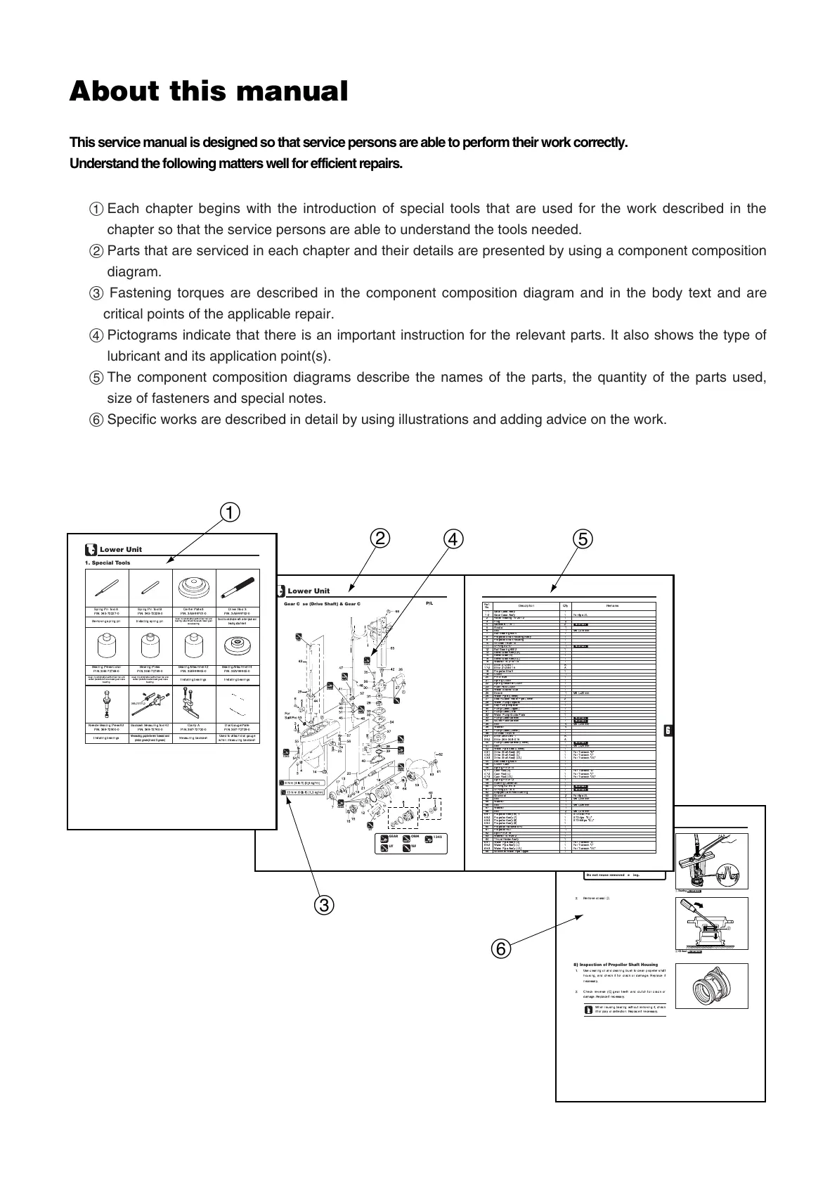
About this manual
This service manual is designed so that service persons are able to perform their work correctly.
Understand the following matters well for efficient repairs.
1 Each chapter begins with the introduction of special tools that are used for the work described in the
chapter so that the service persons are able to understand the tools needed.
2 Parts that are serviced in each chapter and their details are presented by using a component composition
diagram.
3 Fastening torques are described in the component composition diagram and in the body text and are
critical points of the applicable repair.
4 Pictograms indicate that there is an important instruction for the relevant parts. It also shows the type of
lubricant and its application point(s).
5 The component composition diagrams describe the names of the parts, the quantity of the parts used,
size of fasteners and special notes.
6 Specific works are described in detail by using illustrations and adding advice on the work.
MFS4-5-6Ech00110422.qxd 11.4.22 6:14 PM ページ2

 Loading...