7
・EVENT OUTPUT: Process variable(PV) to be used as Event Output, Time Signal and End Signal.
: PV abnormal... In case Input indicates "Over" or "Under" by the cut-off of wire and short-circuit,
Event Output turns ON.
: Stand-by sequence...After starting operation of steps, Event Output does not turn ON unless the
process variable(PV) reach the value of OFF stage of Event Output.
: Event Output Hold...Event Output holds "ON" stage unless altering setting of additional function or
resetting the power.
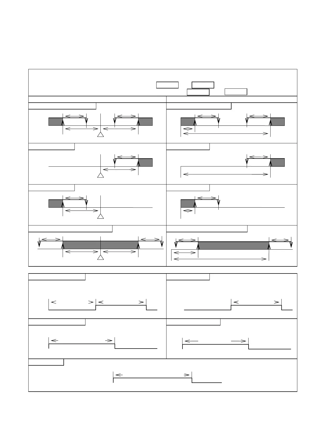
Process variable(PV) Event Output: Starts Event Output function by setting of SV deviation or Absolute Value
against Process variable(PV). On the PV side indicator at "ON" stage, Outpiut1
indicates alternately PV and
,
and Output 2 indicates alternately PV and
.
Setting Value(SV) deviation(Example for Event Output 1) Absolute Value(Example for Event Output 1)
1) High and Low limit 5) High and Low limit
2) High limit 6) High limit
3) Low limit 7) Low limit
4) High and Low limit range 8) High and Low limit range
・Time Signal, End Signal
Time Signal 1, 2 Time Signal 5
At step operation, Event Output turns ON
after passing ON Delay Time and turns OFF
after passing OFF Delay Time.
ON Delay time OFF Delay time
Event Output turns ON while Wait zone.
(Refer to page 6 Wait function)
Time Signal 3, 4 Time Signal 6, 7
Event Output turns ON when step operates and
turns OFF after passing Time Signal ON time.
Event Output turns ON when time signal reach
Wait zone and turns OFF after passing Time.
End Signal
Event Output turns ON after finishing pattern, and turns OFF after passing End Signal ON time.
P1C P1C
P1L P1H
SV
P1C
P1H
P1H
P1H
SV
P1C
P1L
SV
P1C P1C
P1L
P1C P1C
P1L
P1H
P1H
SV
P1C P1C
P1L
O℃(
)
P1C
O℃(
)
P1C
P1L
O℃(
)
O℃(
)
ON
OFF
ON
OFF
WAIT ZONE
△ STEP START
ON
ON
OFF
OFF
SIGNAL ON
END SIGNAL ON TIME
△ WAIT ZONE
△ PATTERN FINISH
ON
OFF
TIME SIGNAL ON
△ STEP START
 Loading...