2
2. INSTALLATION METHOD AND PARTS INDICATION
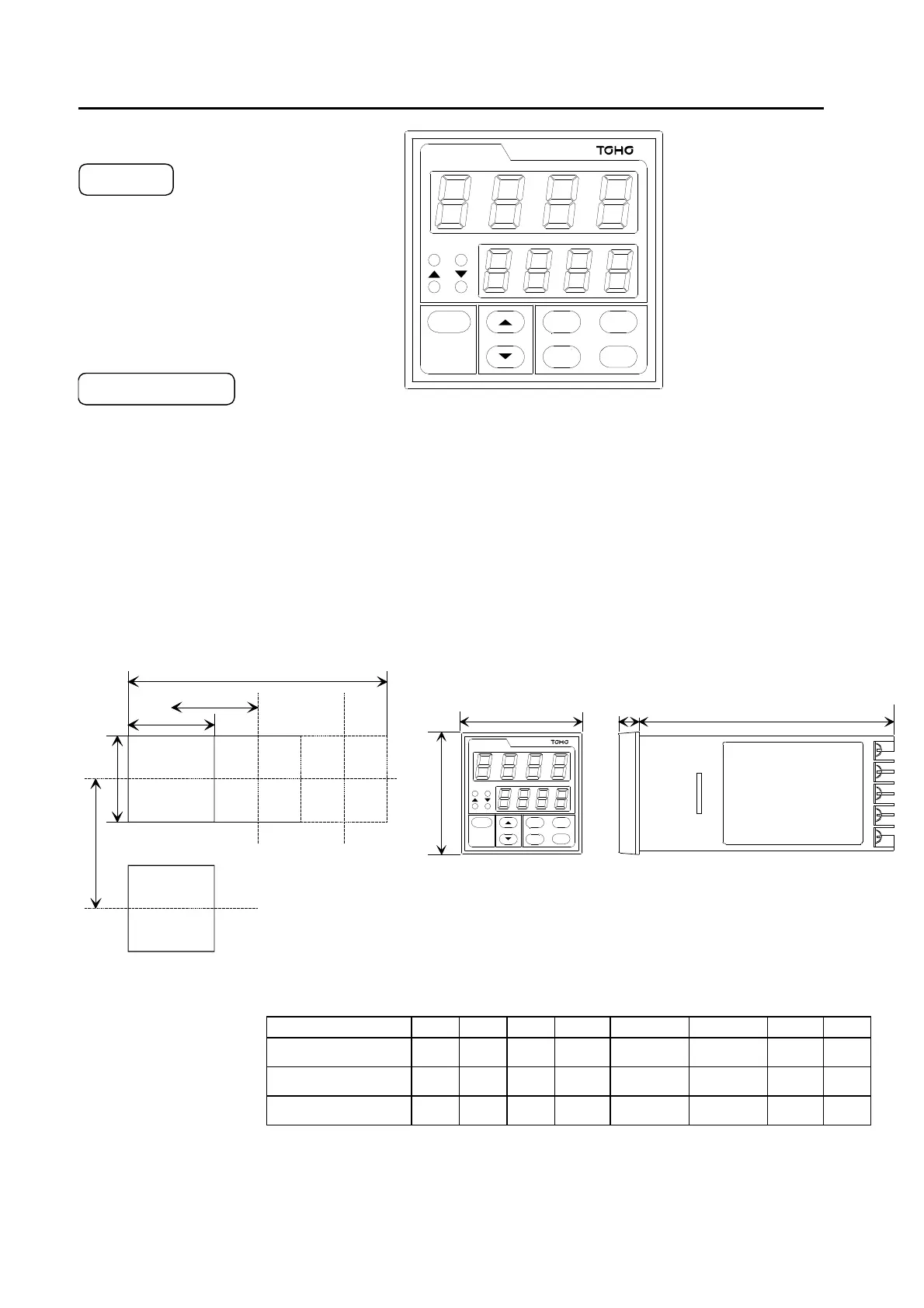
2.1 Name of Parts and Definition
RUN :Light On at RUN mode Indicate PV
OUT :Light On when output (Process Variable)
of main controller. Blink Light on
according to the operation volume
at continuous proportion. Indicate SV
▲ :Light On when set value goes up. (Setting Value)
▼ :Light On when set value goes down.
MODE : Changing the display in each mode.
▲&▼ : Changing set values
TIME/TEMP : Changing "TIME" or "TEMPERATURE" indicate
RUN/STOP : Changing Reset mode or Run mode
PTTN/STEP : RUN mode→Changing PTTN/STEP confirmation mode
RESET : RUN mode→RESET mode
The details of Operation Keys to be referred to "6.OPERATION FLOW AND PARAMETER INFORMATION".
2.2 DIMENSIONS(Panel Cut) 2.3 OUTER DIMENSIONS
P V
SV
RUN OUT
TTM - 3 0 4
MODE
TIME
TEMP
PTTN
STEP
RUN
STOP
RESET
※L
more than d
a
b
more than c
C
D
A
B
PV
SV
RUN OUT
TTM - 3 0 4
MODE
TIME
TEMP
PTTN
STEP
RUN
STOP
RESET
MODEL A B C D a b c d
TTM-304 48 48 8 100
45
0
0 6
−
+ .
45
0
0 6
−
+ .
60 48
TTM-305 96 48 11 80
45
0
0 6
−
+ .
92
0
0 8
−
+ .
120 48
TTM-309 96 96 11 80
92
0
0 8
−
+ .
92
0
0 8
−
+ .
120 96
※In case of Continuous Mounting to N:L=(d×N-3)
−
+
0
1
CART OF PANEL CUT & OUTER DIMENSIONS
 Loading...