21
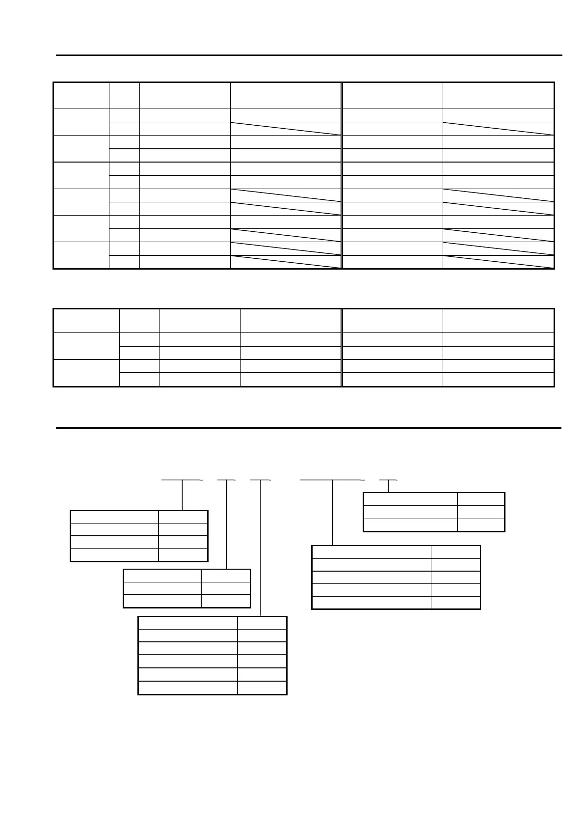
7.SETTING RANGE AND INDICATION RANGE TABLE
7.1 Setting range and Indicating range of Thermocouple input
Input
type
Setting range
Setting range
(with decimals)
Indication range
Indication range
(with decimals)
℃
0 ~ 1300 0.0 ~ 999.9 -40 ~ 1372 -40.0 ~ 999.9
K (JIS)
(IEC)
0 ~ 2500
-40 ~ 2501
℃
0 ~ 800 0.0 ~ 800.0 -31 ~ 850 -31.0 ~ 850.0
J (JIS)
(IEC)
0 ~ 1450 0.0 ~ 999.9 - 24 ~ 1563 -24.0 ~ 999.9
℃
-200 ~ 400 -199.9 ~ 400.0 -231 ~ 407 -199.9 ~ 407.0
T (JIS)
(IEC)
-330 ~ 750 -199.9 ~ 750.0 -385 ~ 765 -199.9 ~ 765.0
℃
0 ~ 1700
0 ~ 1755
R (JIS)
(IEC)
32 ~ 3100
32 ~ 3192
℃
0 ~ 1300 0.0 ~ 999.9 0 ~ 1335 0.0 ~ 999.9
N (JIS)
(IEC)
32 ~ 2372
32 ~ 2435
℃
0 ~ 1800
-20 ~ 1820
B (JIS)
(IEC)
32 ~ 3270
-4 ~ 2435
7.2 Setting range and Indicating range of R.T.D.
Input type
Setting range
Setting range
(with decimals)
Indication range
Indication range
(with decimals)
℃ -199 ~ 500 -199.9 ~ 500.0 -199 ~ 539 -199.9 ~ 539.1
Pt100(JIS)
(IEC)
-199 ~ 950 -199.9 ~ 950.0 -199 ~ 999 -199.9 ~ 999.9
℃ -199 ~ 500 -199.9 ~ 500.0 -199 ~ 529 -199.9 ~ 529.0
JPt100(JIS)
-199 ~ 950 -199.9 ~ 950.0 -199 ~ 984 -199.9 ~ 984.4
8.ORDERING INFORMATION
TTM - 3□□-□-□N-□□□-□
Front size (mm) Symbol
48 x 48 04
96 x 48 05
96 x 96 09
Option Symbol
Event output 1 A
Event output 2 B
RUN signal input E*1
Communication(RS-485) M*1
Input Symbol
Thermocouple 0
R.T.D. 1
Output Symbol
Relay contact R
SSR drive voltage P
1 ~ 5V DC
F
0 ~ 10V DC
G
4 ~ 20mA DC
I
Power Symbol
85V~264V AC
24V AC or V DC
24
*1 RUN signal input and Communication cannot
be adopted at one time.
 Loading...