Document Ref 903158-001 Page 9
Component Technical Manual MA26 MP-T1 Meter for Fuel Dispensers
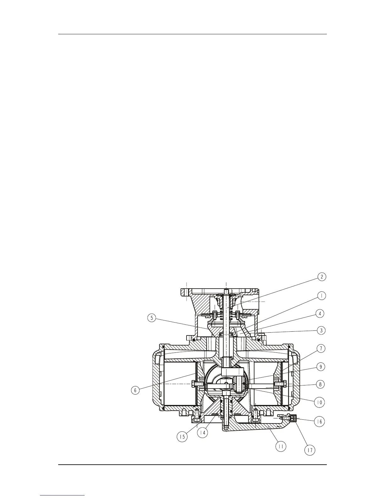
1.1.6 METER OPERATION
The fuel enters the meter via the intake orifice (5) and flows up to the valve (3),
where it applies pressure to the piston (7), while the piston (6) linked to the
former by the connecting rod (8) is in communication with the exhaust orifice
via the opening (4) of the rotary valve (3). Both perpendicular pistons that are
linked to the connecting rod (9) operate under the same conditions, offset by
90°.
Inside the connecting rods (8 and 9), two rolls (10) are mounted on the crankshaft
(2). The upper crankshaft pin drives the distribution valve (3) through a peg (1)
located on the crankshaft, transmitting the rotary movement to the indicating
device.
1.1.7 ADJUSTMENT
Capacity can be adjusted by varying the piston stroke. The device contains a
central cam (13) with four ramps, each one acting successively on the four
pistons. Travel can be adjusted by using a lever (11) to turn the cam around its
axle (12). The lever may be positioned firstly in relation to the position of the
cam, via a square section part (14). Its position on the notched part (15) may be
adjusted using the screw (16) which acts as a positioning pin.
The lever is designed in such a way that, whatever its position on the notched
part, the screw (16) is always hidden. It is protected by the sealing device (17).
The clearance needed for adjustment is obtained by the clearance between the
rollers and the connecting rod sliders.
Each notch on the notched part modifies the meter’s cylinder capacity by 0.1%
Access to the adjusting device is made impossible by a seal.
Issue A