Page 10 Document Ref 903158-001
MA26 MP-T1 Meter for Fuel Dispensers Component Technical Manual
1.2 MP-T1 Pulser
1.2.1 SYSTEM DESCRIPTION
The MP-T1 pulser is part of the measurement transducer used in a fuel dispenser.
The task of this unit is to detect and to indicate when a volume of 1cl fuel has
left this unit. Below is a short description of the different parts of the
measurement transducer.
This device will be placed in series with the nozzle of a dispenser. It converts
the fuel flow into rotations of a shaft. One rotation of the MA26 volume meter
represents a fuel flow of 70cl.
The MP-T1 housing is placed on top of the volume meter. This housing contains
the MP-T1 electronics (placed on a support), 3 gear wheels and a magnetic
disc. The rotation of the volume meter shaft will be conveyed by the 3 gear
wheels to the magnetic disc. The speed ratio volume meter shaft:magnetic disc
= 1:3.5.
So one turn of the disc represents 20 cl.
The electronic outputs of the MP-T1 pulser, which contain “cl” pulses, will
drive the inputs of the calculator.
One or more pulsers, each with a 4 wire link, are connected to the calculator.
This link contains two pulse lines and two power lines to supply the pulser
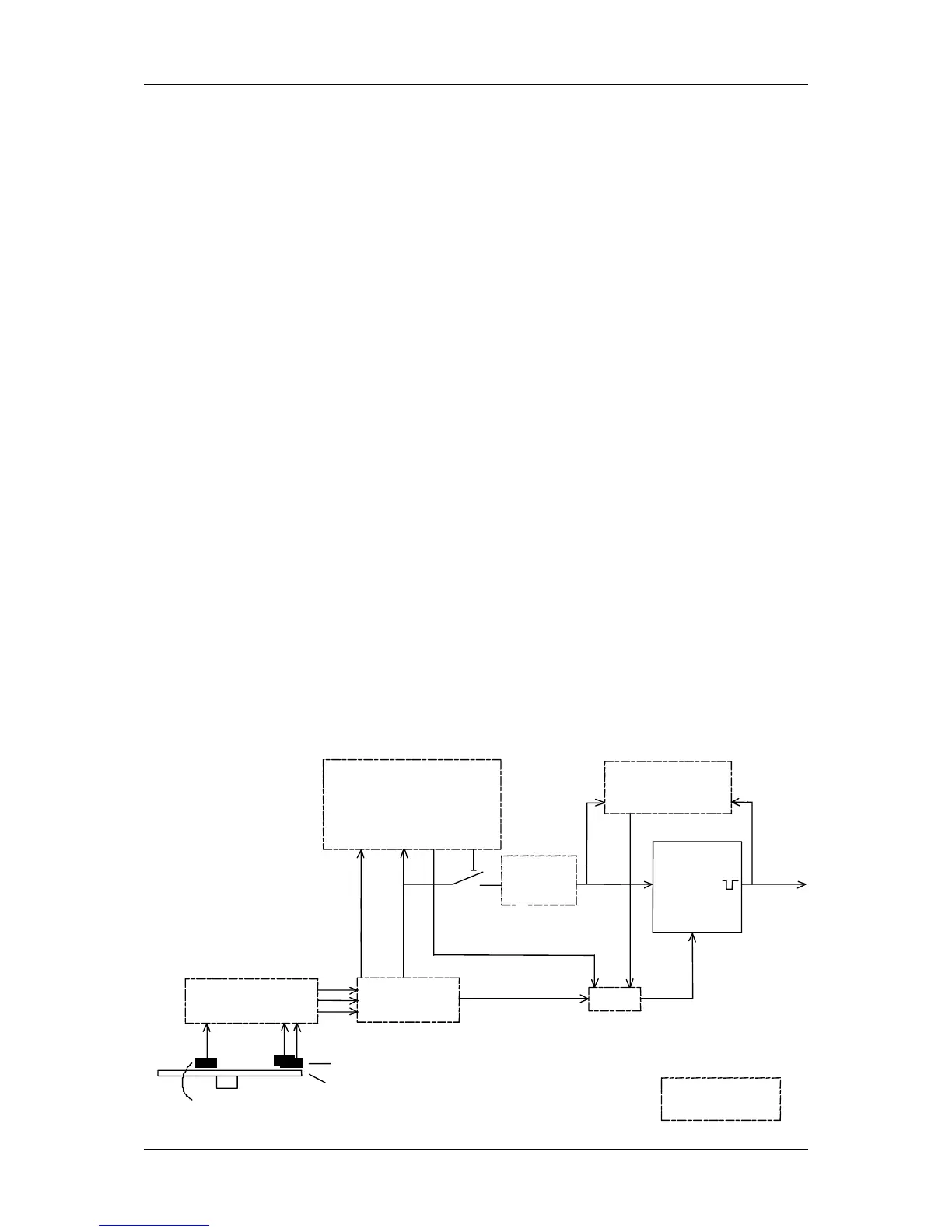
1.2.2 FUNCTIONAL PARTITION OF THE MP-T1 ELECTRONICS
The MP-T1 electronics take care of the translation of the magnetic field changes
into proper “cl” pulses needed for the calculator. The MP-T1 electronics can be
divided into the following functional blocks. The functions of the different blocks
are described on the following pages. All digital functions of the MP-T1
electronics are integrated in an Asic.
-
T
backward flow
count
(centilitres)
cl=0
comparator
output
driver
timer
sequence
detector
digital
filter
cl=20+
backward
count
error
Asic parts
forward
count
hall effect sensor (fault detection)
magnetic disc
hall effect sensors (direction)
sensor defect
overflow
not equal
disable
pulse line
A and B
Issue A