Do you have a question about the Tokyo Hy-Power HL-700B and is the answer not in the manual?
Compact and lightweight unit due to small heat sink and DC fan for mobile use.
No warm-up needed, instant start, wide-band amplifier requires no final tuning.
10W/100W input selection allows for 600W (PEP) or 400W output configurations.
Incorporates six types of protection for enhanced reliability and reduced trouble.
Monitors transmission power (Pf), reflected power (Pr), and source voltage (Vc).
Integrated filters on amateur bands (3.5-28 MHz) prevent TVI generation.
Selectable time lags for AM/FM (momentary) and SSB/CW (one second) operation.
Operates across amateur bands: 3.5, 7, 14, 21, and 28 MHz.
Supports SSB, CW, AM, and FM reception modes.
Features selectable input power levels of 100 W or 10 W.
Details output wattage for SSB, CW, FM, and AM based on input power.
Undesired radiation is specified as -40 dB or less.
Third cross modulation distortion is rated at -30 dB or less.
Input and output impedance is set at 50 ohms.
Uses standard M-type connectors for input and output.
Utilizes a forced-air cooling system for thermal management.
Requires a DC 13.8 V power supply.
Draws up to 70 A of current at 500 W output.
Includes spare fuses, power cable, remote plug, and RF cable.
Measures 300(W)x100(H)x342(D) mm, weighing approximately 8 kg.
Filters in the output section for amateur bands to prevent TVI.
Detects waves for power metering & protection, uses a directional coupler.
High power output (600W PEP) using THP-120 transistors.
Functions as driver for final stage, ensures good frequency response.
Compact forced-air cooling system with DC line flow fan.
Manages transmission/reception switching and time lags.
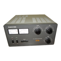
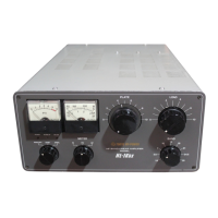
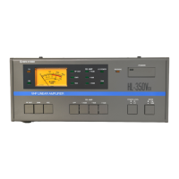
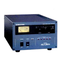
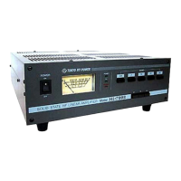
Details Power switch, Pf/Pr/Vc meter, POWER LED, TX LED, WARNG LED, BAND switches, Meter selector.
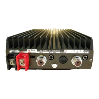
Describes XCVR (IN), REMOTE, ACC, DC 13.8V (IN), ANT (OUT) ports.
Explains SW3, SW1, SW2, SW4 switches and VR6 volume control.
Specifies 13.8 VDC, 70A capacity, and recommended external units.
Use durable antenna for 600W output, prepare SWR meter.
Use 50-ohm impedance cable (8D2V or equivalent).
Compatible with HF SSB, CW, RTTY, FM transceivers (10W or 100W).
Ensure adequate space for cooling, avoid high temp/humidity.
Connect for stable switching and proper output level.
Ensure battery/generator capacity; keep engine running for charging.
Connects transceiver, power supply, and antenna using diagrams.
Steps to measure and adjust antenna SWR for optimal performance.
Setting switches and controls before powering on the unit.
Turning on power, checking voltage, setting transceiver, adjusting ALC.
Setting modes, observing meters, and handling protection systems.
How the unit passes signals when powered off.
Correct voltage (13.8V DC), amperage, and power cord usage.
Use durable antenna, ensure proper grounding to avoid oscillation.
Avoid high temperatures, direct sunlight, and ensure ventilation.
Match transceiver drive power (10W/100W) to avoid overdrive.
Do not disturb or modify internal components due to precision assembly.
Lists symptoms (No power, Low power), causes, and remedies.
Details input voltage (100VAC), output voltage (13.8V), and amperage (70A).
Details input voltage (24VDC), output voltage (13.8VDC), and amperage (70A).
| Frequency Range | 1.8 - 54 MHz |
|---|---|
| Output Power | 700W PEP |
| Gain | 13 dB |
| Cooling | Forced air |
| Weight | 12 kg |
| Supply Voltage | 13.8V DC |
| IMD | -30 dB |
| Mode | SSB, CW |