Do you have a question about the Tokyo Hy-Power HL-2K and is the answer not in the manual?
Describes the core amplifier design and vacuum tubes.
Highlights the robust power supply system.
Details the supported ham bands.
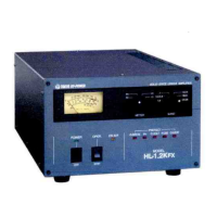
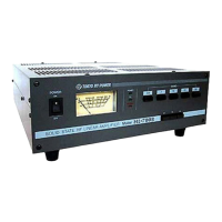
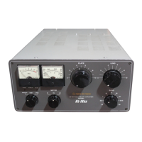
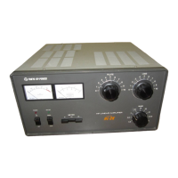
Explains the plate current and multi-function meters.
Describes the fan's operation for tube longevity.
Notes the fine-tuning capability for capacitors.
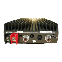
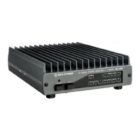
Mentions the durable build for heavy components.
Details the efficient cooling mechanism.
Explains the safety feature for high voltage.
Lists supported ham bands and operating modes.
Defines input power and RF output power.
Specifies plate voltage, current, and impedance.
Identifies vacuum tubes, semiconductors, and operation class.
Details supported AC voltages and cooling.
Provides dimensions, weight, and accessories.
Explains how to set voltage taps for different AC inputs.
Notes that the AC plug is not supplied.
Mentions the 3.15A fuses used.
Warns about potential damage from misconnecting voltage taps.
Controls power, fan delay, and meter selection.
Sets operating band and adjusts plate/load tuning.
Describes the plate current and multi-function meters.
Explains the ON AIR and POWER pilot lamps.
Connects antenna, ground, ALC, and remote control.
Input for RF signal from transmitter.
Connection for AC power.
Location for fuses.
Adjustment for ALC output voltage.
Lists and identifies key internal components by number.
Lists and identifies components visible from the bottom.
Details RF signal path and amplification.
Describes RF output, power measurement, and ALC.
Explains fan off-delay and high-voltage power supply.
Safety precautions before starting tube installation.
Guide for physically inserting tubes and attaching caps.
Steps for installing the second tube and reassembling.
Emphasizes careful handling of vacuum tubes and screws.
Guides initial physical connections and power setup.
Sets band switches and initial tuning capacitor values.
Describes turning on and switching to transmit mode.
Guides tuning for output power and plate current dip.
Fine-tuning for optimal output and using ALC.
Advises on the duration for tuning adjustments.
Importance of 50-ohm load and VSWR.
Requirements for proper ventilation and placement.
Recommendations for AC voltage and power source.
Safety procedures when accessing internal parts.
Warning about interrupting fan operation.
Advise on periodic cleaning to maintain performance.
Importance and method of proper grounding.
Recommendation for reducing power in certain modes.
Troubleshooting steps for power issues.
Causes and solutions for repeated fuse blowing.
Diagnosing fan operational problems.
Issues affecting plate voltage and current readings.
Fixing low output power and "ON AIR" status failures.
Troubleshooting reception issues in OPER mode.
Recommended power limits and pi network tuning.
VSWR impact and band switch caution.
Operation without load and outside amateur bands.
| Brand | Tokyo Hy-Power |
|---|---|
| Model | HL-2K |
| Category | Amplifier |
| Language | English |