22
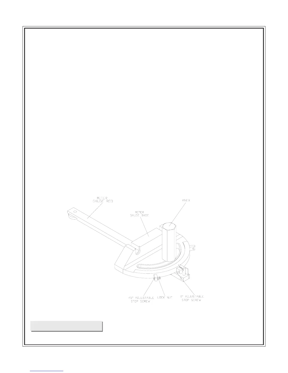
See Figure 25.
You can set the miter gauge at 0
o
and plus or
minus 45
o
with the miter gauge stop pin and
adjustable stop screws.
Note:The miter gauge provides close accuracy in
angled cuts. For very close tolerancesm,
test cuts are recommended.
Loosen knob and pull out on stop pin to rotate
miter gauge base past stop screws.
Loosen the lock nut of the 0
o
stop screw at
the stop pin with a 8mm wrench.
Place a 90
o
square against the miter gauge
rod and the miter gauge base.
If the rod is not square, loosen the knob,
adjust the rod, and tighten the knob.
Adjust the 0
o
stop screw until it rests against
the stop pin.
Adjust the plus and minus 45
o
stop screws
using a 45
o
triangle and the steps above.
`
Fig.25
ASSEMBLY DIAGRAM


 To Next Page