PRELIMINARE
8a 9a
S1,SA
A1_2
x
x
S1
V0
Fig.
8b
Fig.
9b
Mi2
G
M2
G
Fig.
12a
M1
M2
V2
V1
D1
SA
Fig.
11b
SA
0V
Fig.
10b
Fig.
12b
T1
D1
V1
Fig.
13b
V2
Fig.
14b
S1
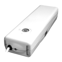
ANGULAR INSTALLATION
I f n e c e s s a r y a d j u s t
(screwing or unscrewing)
the eyebolt "T1".
Insert the "M2" clamps in
the "G" guides on the sides
of the actuator.
7) Fig.14b- Let the actuator
slide along its axis until such
a pressure is performed on
the seals as to obtain a good
clo sing of the w indow
f r a m e . T h e n , fi x t h e
screws“V2”.
0) Set hypothetical stroke
end, for the c o m plete
opening of the window, Fig.
15 to 18.
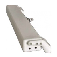
3) Fig.10b- Drill the frame of
the window and fix the
actuator support bracket
"SA" with the screws "V0",
m a k i n g s u r e t h a t t h e
brackets are aligned.
4) F ig.11b- Moun t the
internal clamps "M1" and
"M2" on the "SA" bracket
using the "V2" screws.
8) Perform the electrical
connections as described,
see, Cap. 5.3.
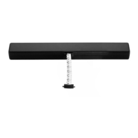
6) Fig.13b- After having
verified that the window
frame is in closing position,
fix the thrust rod head "T1"
to the bracket "S1" with the
screw "V1" and of the nut
"D1";
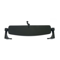
1) Fig. 8b- With a pencil
draw the centre line X of the
window frame;
5) Fig.12b- Make sure that
t h e a c t u a t o r r o d h a s
completely retracted into
the actuator.
2) Fig.9b- Use a suitable
drill to drill the movable part
of the frame and fix the
b r a c ket " S 1 " w i th th e
screws "V0".
C160
USO E FUNZIONAMENTO -6
S80
10- DRAWINGS / INSTALLATION INSTRUCTIONS
22
INSTALLATION AND USE INSTRUCTIONS
 Loading...