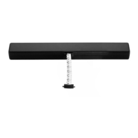
Fig.
8c
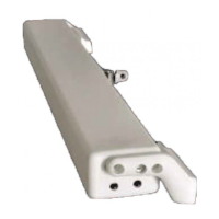
Fig.
9c
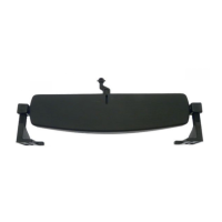
Fig.
10c
1 REMOVE
1) Fig.8c-Define the hypothetical stroke “L1” .
INSTALLATION INSTRUCTION
If necessary adjust (screw-unscrew) the thrust rod head “T1”.
3) Fig.14c- Make a hole in the window with a suitable drill and fix the bracket “S2” with “V0” screws.
4) Fig.15c- Fix the thrust rod head “T2” to the bracket “S2” using “V1” screw and “D1” nut.
5) Fig.16c- Fix the thrust rod head “T1” to the winch using “V1” screw and “D1” nut.
2) Set the final stroke “L1”, see Fig. from 9c- to13c-.
6) Perform the electrical connections as described, see, Cap. 5.3.
25
INSTALLATION AND USE INSTRUCTIONSINSTALLATION AND USE INSTRUCTIONS
C160
USO E FUNZIONAMENTO -6
S80
DRAWINGS / INSTALLATION INSTRUCTIONS -10
 Loading...