User Manual of MT06
-
7
-
Please select experienced technicians to install this system.
The installation should be carried in the working condition for this system.
Install this system in a secret place.
Prevent this system from dust and humidity.
Connect the wires of other wires, leave the plug unplugged.
Fixing, wiring connecting, binding should be carried on carefully.
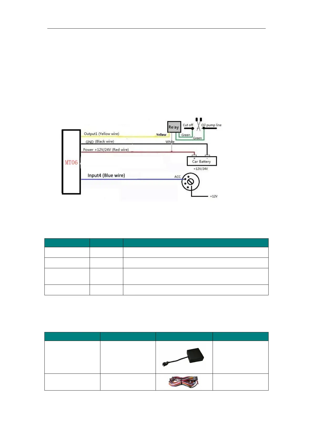
6.1 4-p wires instruction
DC in (power source). Input voltage: 9V-24V, 12V suggested.
Digital Input 4 (positive triggering), E.g. detecting status of
ACC on/off
E.g. Connect relay to cut off engine or fuel
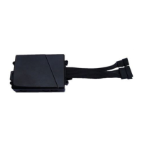
6.2 Standard accessories of GPS tracker MT06
Mainly used to
connect to the vehicle