Installation Instruction
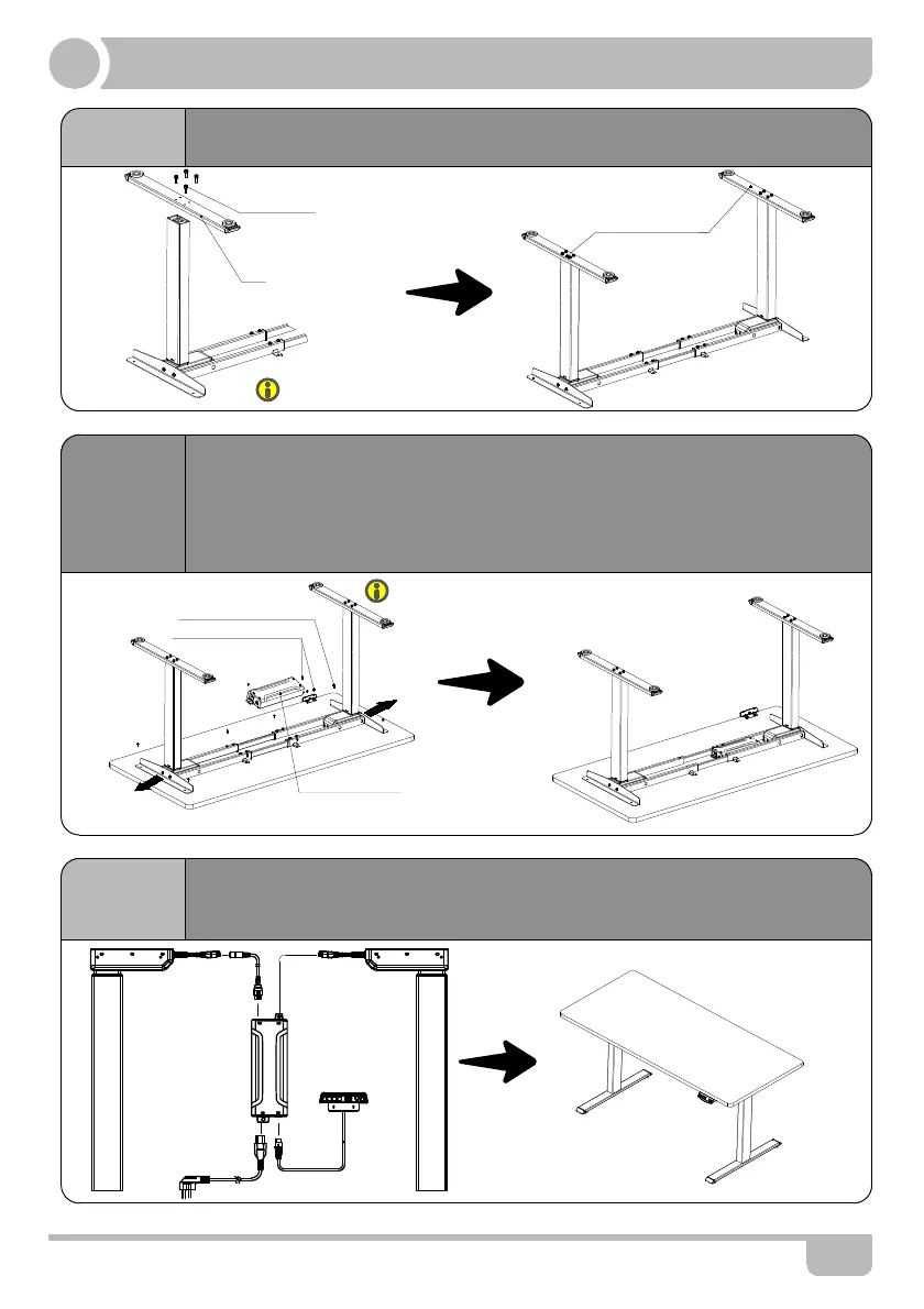
STEP 4
STEP 5
STEP 6
· Install the handset on suitable position of desktop edge to avoid
interference with humans or chairs.
· Tidy up all the power cables, and fasten with cable clip.
▲The frame width is adjustable: 1088~1500mm, which is suitable for different desktop.
4
M6*30 Screw
Foot
ST4.8x16 Tapping Screw
Avoid excessive tightening screws
Fasten the screws
· Check both side of desktop before placing the base on the bottom side of the
desktop.Adjust the suitable width. It is suggested that the two sides of the frame
side brackets are 2 inch from the edge of the desktop and fasten screws.
· Mounting bracket is set on the same side with the handset, between the right
tube and left tube. As shown below,connect related parts, including control
box,extension cable and power cord.
Control Box
· Line up the screw holes on the feet and columns.
· Fasten the screws.
ST3.5x16 Tapping Screw
*Board need to be purchased separately.
*If you have bought the board from TOPSKY, you can
use the M6*16 screws and wrench we supplied.
Control Box and Handset still need tapping
Screws(Suggest use electric drive.)
M 1 2
3