Installing the Hose Guide (continued)
G410292
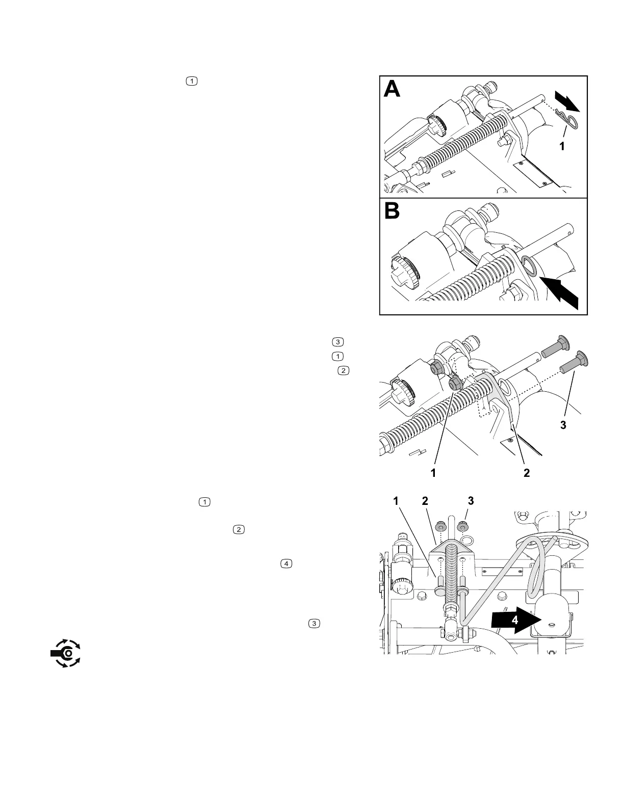
1. If the hairpin is installed in the rear hole of
the compensation-spring rod, remove the
hairpin and insert it in the hole next to the
bracket.
G410293
2. Remove the 2 flange locknuts (3/8 inch)
and 2 carriage bolts (3/8 x 1-1/4 inches)
that secure the turf-compensator bracket to
the cutting-unit frame.
G410311
3. Align the studs of the right hose guide with
the holes in the cutting-unit frame and the turf-
compensator bracket
.
Note: Ensure that the support loop of the hose
guide aligns toward the center
of the
machine.
4. Assemble the hose guide and turf-
compensator bracket to the cutting-unit frame
with the 2 flange locknuts (3/8 inch)
.
5. Torque the locknuts to 37 to 45 N∙m (27 to 33
ft-lb).
3466-702A Page 3–5 Setup: Installing the Cutting Units
 Loading...


