g024656
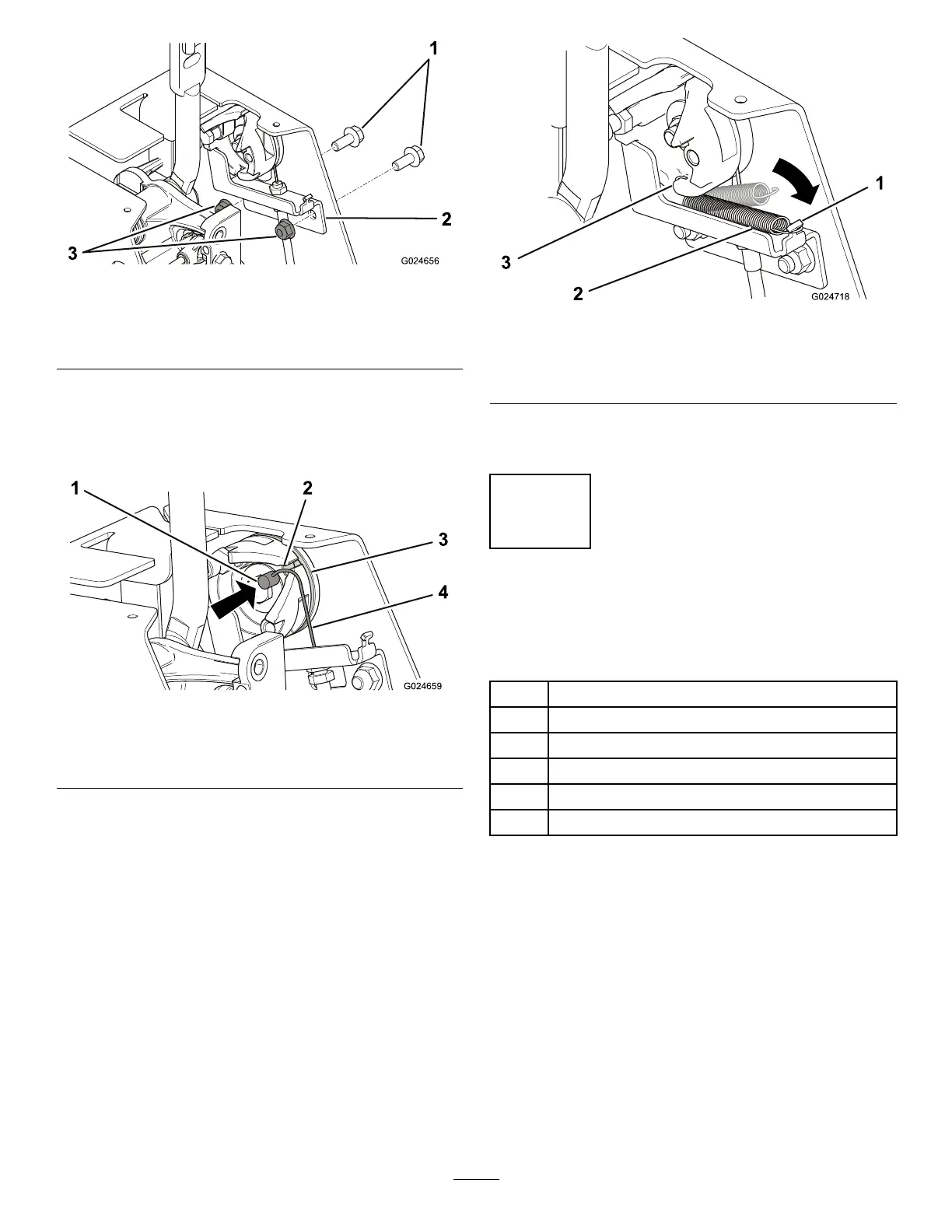
Figure9
1.Bolts(5/16x3/4inch)3.Flangenuts(5/16inch)
2.Cambracket
2.Securethebracketwith2bolts(5/16x3/4inch)
and2angenuts(5/16inch).
3.Rotateeachcamtowardthecenterofthe
machine(Figure10).
g024659
Figure10
1.Cylindricalend3.Slot
2.Hole
4.Cable
4.Witheachcam,insertthecylindricalendofthe
cableintotheholeinthecam,andslidethe
cableintotheslot(Figure10).
5.Sliponeendofaspringintotheslotatthe
bottomofthecam,andhookthespringontothe
camasshowninFigure11.
g024718
Figure11
1.Tab
3.Slot
2.Spring
6.Hooktheotherendofthespringoverthetabon
thecambracket(Figure11).
5
RoutingandMountingthe
Cables
Partsneededforthisprocedure:
2
Cabletie
2
Bolt(5/16x3-1/2inch)
4Frictionwasher
2
Spacer(5/16x3/8inch)
2
Spacer(5/16x1inch)
2
Flangenut(5/16inch)
Procedure
1.Routeeachcablefromthecamdownwardunder
thecontrol-leverlinkage,andthenbackward
alongtheframeasshowninFigure12and
Figure13.
5