g024664
Figure12
Somepartsshownastransparent
1.Cable(left-handsideshown)
g024683
Figure13
1.Cable(left-handsideshown)
2.Secureeachcabletotheframebyattachinga
cabletiethroughtheholeintheframenearthe
control-leverlinkageoneachside(Figure14).
Important:Donotattachthecabletietothe
control-leverlinkage.
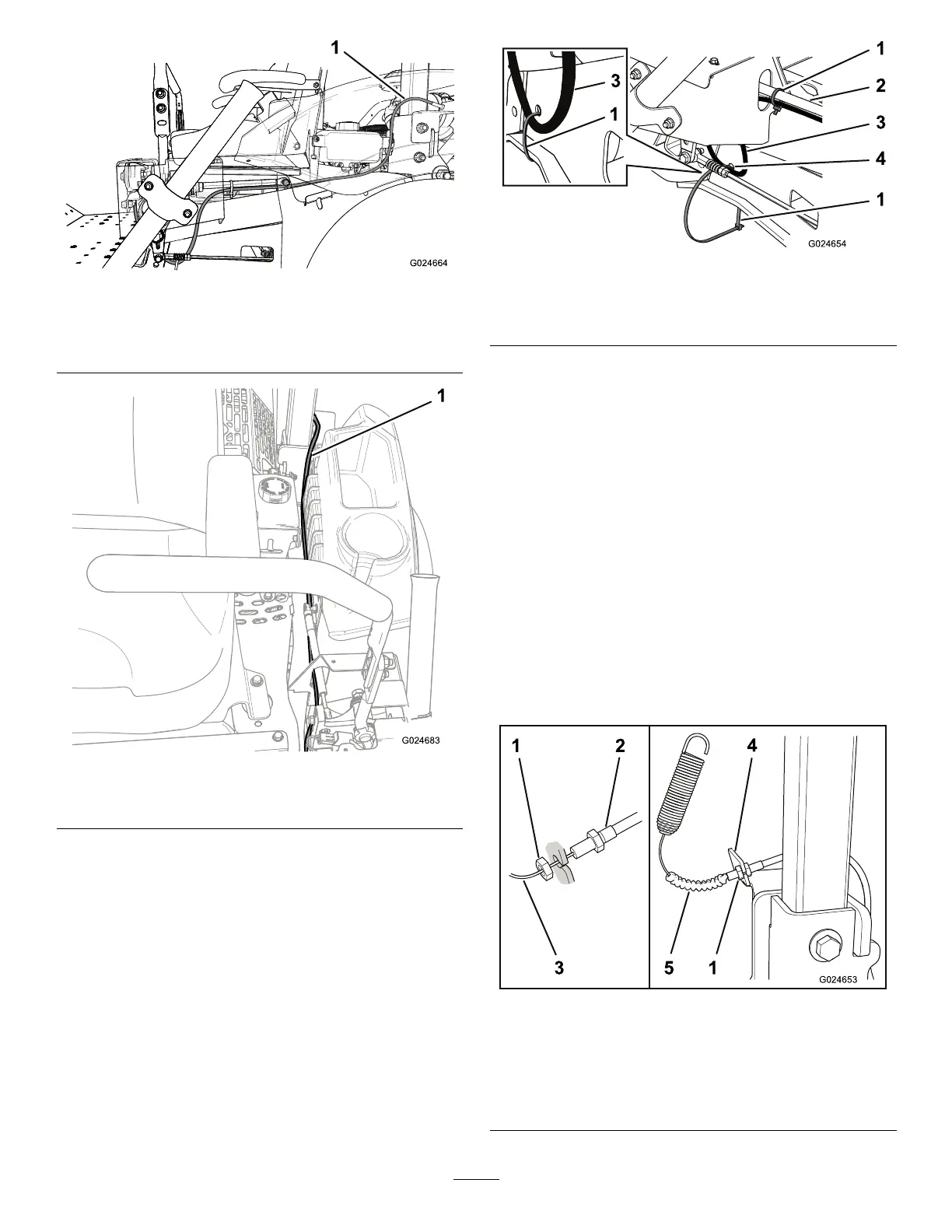
g024654
Figure14
1.Cabletie3.Cable
2.Control-leverdamper
4.Hole
3.Useacabletietosecureeachcabletothe
control-leverdamperoneachside(Figure14).
4.Installeachcabletothecorrespondinglift
bracketasfollows(Figure15):
A.Slidethebellowsawayfromthethreaded
tting.
B.Removethejamnutnearestthevisiblepart
ofthecable.
C.Insertthethreadedttingintotheopening
oftheliftbracket.
Important:Positionthenutssothat
thethreadedttingiscenteredinthe
bracket.
D.Tightenthejamnuttosecurethecable
assemblytotheliftbracket.
E.Installthebellows.
g024653
Figure15
Left-handsideshown
1.Jamnut
4.Cambracket
2.Threadedtting5.Cablebellows
3.Cable
6