5.Assemblethespringattheendofeachcable
ontoa5/16x3-1/2inchbolt,withashortspacer,
alongspacer,and2frictionwashersasshown
inFigure16.
g024652
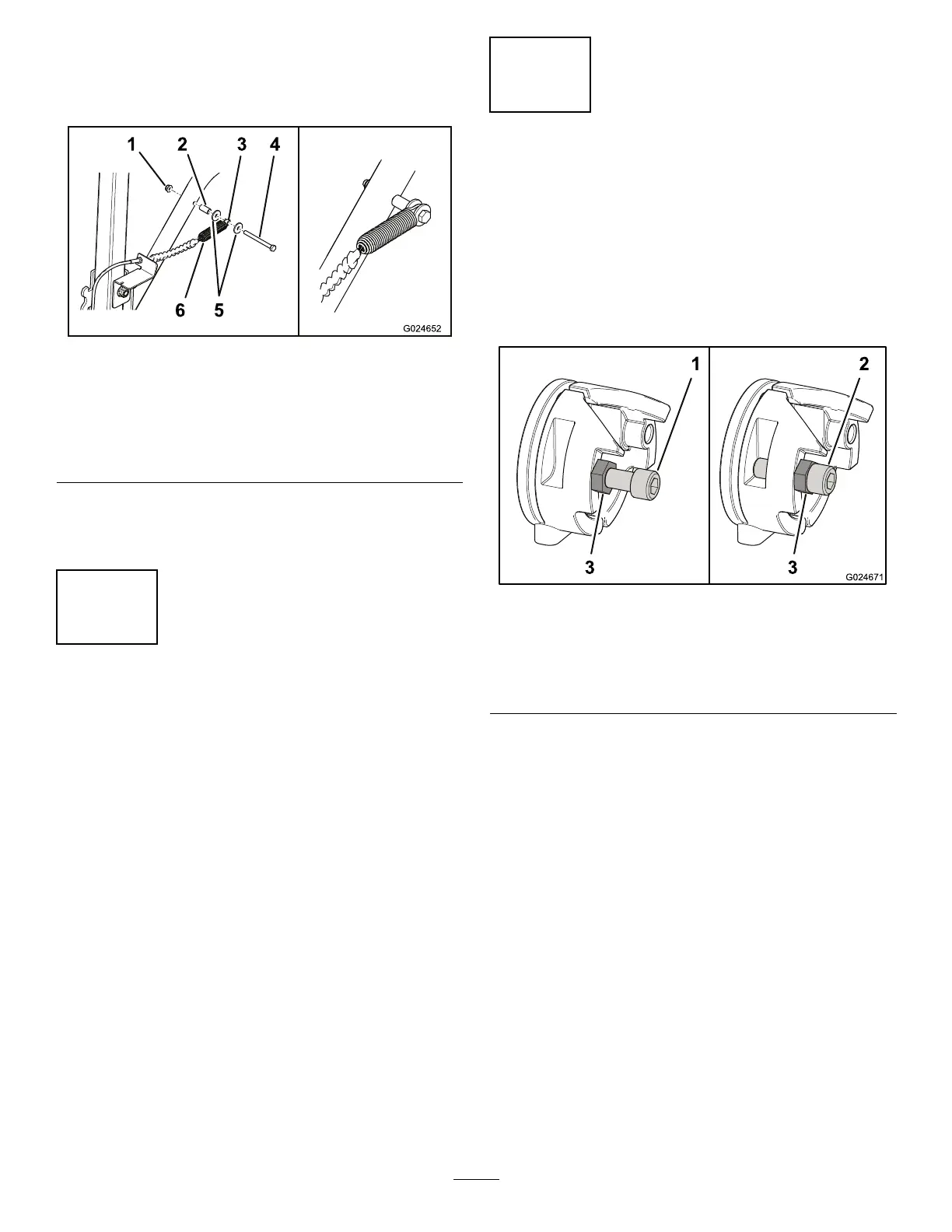
Figure16
Left-handsideshown
1.Flangenut(5/16inch)4.Bolt(5/16x3-1/2inch)
2.Spacer(5/16x1inch)
5.Frictionwashers
3.Spacer(5/16x3/8inch)6.Spring
6.Installtheassembledboltsandcablestothe
attachmentlift,andsecurethemwith2ange
nuts(5/16inch);refertoFigure16.
6
CheckingtheOperationof
theAttachmentLift
NoPartsRequired
Procedure
Important:Keepthecontrolhandlesinthe
neutralposition.Drivingthemachinewhenthe
stopplatesarenotinstalledcouldoverloadthe
inputshaftsofthetransmissions.
1.Sitontheseat,movethecontrolhandlestothe
neutralposition,andsettheparkingbrake.
2.Starttheengine.
3.Lowerandraisetheattachment,andcheck
toensurethattheattachmentliftandthe
speed-limitercablesworkproperly.
Important:Ifthereisanythingthatdoesnot
workproperly,correcttheissuebeforeusing
themachine.
4.Stoptheengine.
7
AdjustingtheSpeedand
theTracking
NoPartsRequired
AdjustingtheSpeed
1.Loosenthejamnutonthesocket-headcap
screwoneachcam(Figure17).
g024671
Figure17
1.Socket-headcapscrew
(slowposition)
3.Jamnut
2.Socket-headcapscrew
(fastposition)
2.Adjustthesocket-headcapscrewsas
necessary.
•Tightenthecapscrewstoincreasethe
speed.
•Loosenthecapscrewstodecreasethe
speed.
3.Tightenthejamnutstosecurethesocket-head
capscrews.
AdjustingtheSlow-speedTracking
1.Drivethemachine,withtheattachmentlowered,
anddeterminewhetherthemachinetracksto
therightortheleft.
2.Adjustthesocket-headcapscrewsas
necessary.
Thedirectiontowardwhichthemachinetracksis
theslowside.Youcanincreasethespeedofthe
slowsideordecreasethespeedofthefastside.
7
 Loading...