Drive System
Maintenance
Adjusting the Self-propel
Drive
If the la wn mo w er does not self-propel or has a
tendency to cree p forw ard when the control bar is
more than 1-1/2 inc hes (3.8 cm) from the handle ,
adjust the wheel dri v e control knob on the rear of
the g ear bo x.
1. Close the door in the la wn mo w er housing and
remo v e the g rass bag .
2. R otate the control knob cloc kwise a half tur n
if the la wn mo w er does not self-propel. If the
la wn mo w er cree ps forw ard, rotate the knob a
half tur n countercloc kwise to loosen the belt
( Figure 26 ).
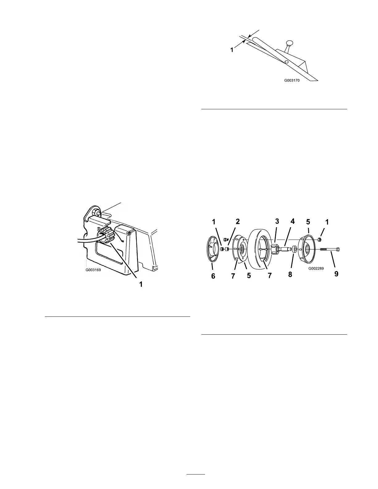
Figure 26
1. Control knob
3. Slo wly pull the la wn mo w er bac kw ard while
y ou g radually mo v e the control bar to w ard the
handle .
Note: T he adjustment is cor rect when the
rear wheels stop tur ning and the control bar
is about one inc h (2.5 cm) from the handle
( Figure 27 ).
Figure 27
1. 1 inch (2.5 cm)
Servicing the Wheels
Removing the Wheels
1. Stop the engine and w ait for all mo ving par ts
to stop .
2. Disconnect the wire from the spark plug
( Figure 13 ).
3. R emo v e the bolt, the wheel spacer , and the
loc kn ut mounting the wheel to the pi v ot ar m
( Figure 28 ).
Figure 28
1. Locknuts
6. Plastic cover (rear wheels
only)
2. Wheel spacer
7. Lug
3. Bearing/hub assembly
8. Bearing (2)
4. Bearing spacer
9. Bolt
5. Wheel half
4. Se parate the wheel halv es from the tire b y
remo ving 4 bolts and 4 loc kn uts ( Figure 28 ).
Note: If y ou remo v e the bearings from
the bearing/hub assembly , remo v e them b y
pressing on the bearing spacer ( Figure 28 ).
Assembling the Wheels
1. P osition the tire onto one wheel half , aligning
the lugs on eac h ( Figure 28 ).
2. Place the bearing/hub assembly into the center
hole of the wheel half . Ensure that the legs of
the hub are positioned o v er the flang e of the
hole ( Figure 28 ).
23