5.DisconnecttheendyokeofthePTOdriveshaft
fromthemowergearboxshaft:
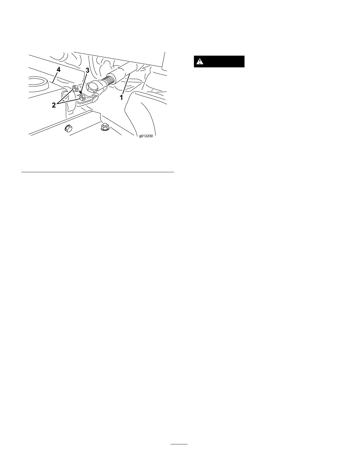
A.Removetherollpinfromtheendyokeandthe
gearboxshaft(Figure4).
Figure4
1.Driveshaft
3.Rollpin
2.Capscrewsandlocknuts4.Gearbox
B.Loosenthe(2)capscrewsandlocknuts(Figure4).
C.Slidethedriveshaftendyokefromthegearbox
shaft.
Note:Raiseandtiethedriveshafttotheframe.
6.Removethe(4)ringpinsandclevispinsthatsecure
theliftchainstotheadjustmentclevisesonthe
mower(Figure2).
7.Slidethemowerawayfromthemachine.
Note:Thefrontofthetractionunitmayhaveto
elevatedtomovethemowerawayfromthemachine.
InstallingtheNewMower
1.Slidethenewmowerunderthecarrierframeofthe
machine.
2.Installthe(4)clevispinsandringpinstosecurethe
mowerliftchainstotheadjustmentclevisesonthe
mower(Figure2).
3.ConnecttheendyokeofthePTOdriveshafttothe
mowergearbox:
A.Alignthesplineandrollpinholesofthedrive
shaftyokewiththegearboxshaft.
B.SlidethePTOdriveshaftendyokeontothe
gearboxshaft.
C.SecuretheendyokeofthePTOdriveshaftto
thegearboxshaftwiththerollpin(Figure4).
D.Tightenthelocknutstosecuretheendyoketo
thegearboxshaft(Figure4).Torquethelocknuts
to175to225in-lb(20to25N-m)
4.Starttheengineandfullyraisethemower.Stopthe
engineandremovethekeyfromtheignitionswitch.
Note:Placeawoodblockorsimilarshimunder
eachlinktoholditintheraisedposition.
CAUTION
Becarefulwhenconnectingthepulllinksto
themachine.Thepulllinktorsionspringsmay
causesomerotationofthepulllinksduring
installation.
5.Alignthepulllinktothecarrierframeandattach
thelinkwiththeretainerpin(Figure2).Securethe
retainerpintotheframewiththeshoulderscrew
(
Figure2).
6.InstalltheHOCpinintotheHOCbracketatthe
desiredheightofcut(Figure3).
7.LubricatethePTOdriveshaftgreasettings.
8.InstallthefuseF1(15amp)intothefuseblock.
LevelingtheMower
LevelingSidetoSide
1.Positionthemachineonalevelsurfaceontheshop
oor.
2.MovethethrottlelevertotheSlowposition,stop
theengine,settheparkingbrake,andremovethe
ignitionkey.
3.Setthemowertothe5inch(127mm)heightofcut
setting.
4.Checkandadjustfrontandreartractionunit
tirepressure;refertoOperator’sManualfor
specications.
5.Checkforbentblades;RefertoCheckingforBent
Blades.
6.Rotatethebladeoneachspindleuntiltheendsface
forwardandbackward.
7.Measurefromtheoortothefronttipofthecutting
edge.
8.Adjustthejamnutssecuringthemoweryokes/chains
tothemoweruntilthemowerislevel(
Figure5).
8