16
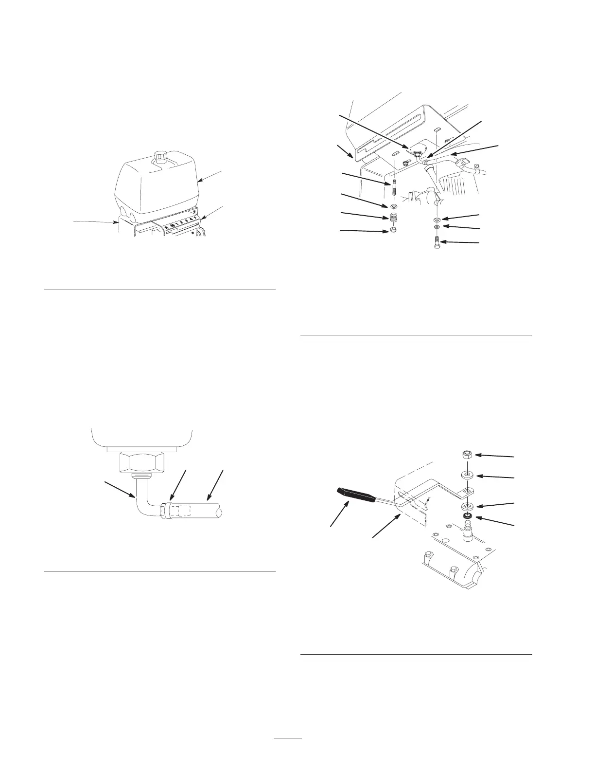
Installing the Shift Lever Plate
and Fuel Tank
1. Remove the bolts and nuts holding the shift lever plate
to the rear frame. Discard these nuts and bolts.
2. Slide the shift lever plate over the shift lever and under
the bottom of the rear frame (Fig. 10).
m–5221
3
1
2
Figure 10
1. Rear frame
2. Shift lever plate
3. Fuel tank
3. Align fuel tank with the top of the rear frame (Fig. 10).
4. Push the fuel line onto the fuel tank connection and
secure it with the hose clamp that is on the fuel line
(Fig. 12).
Note: To ease assembly of the fuel line to fuel tank
connection, apply a light lubricant, such as WD 40, to the
end of the fuel line.
Note: Make sure the fuel line and clamp are on as shown in
Figure 11.
m–6504
2
1
3
Figure 11
1. Fuel line
2. Clamp
3. Fuel tank connection
5. Slide the shift lever plate over the shift lever (Fig. 13).
6. Secure the right side of shift lever plate and fuel tank to
the rear frame (Fig. 12) with 2 bolts (5/16 x 7/8 inch),
lock washers (5/16 inch) and washers (5/16 inch)
(Fig. 12).
7. Secure the left side shift lever plate and fuel tank to the
rear frame (Fig. 12) with washers (5/16 inch), springs
and locknuts (5/16 inch) (Fig. 12).
Note: Tighten left side of shift lever plate until it is
completely tight and then unscrew locknut one full turn.
This will allow the spring to work.
3
8
7
3
6
2
1
5
4
10
9
m–6465
Figure 12
1. Bolt, 5/16 x 7/8 inch
2. Lock washers, 5/16 inch
3. Washer, 5/16 inch
4. Fuel line
5. Hose clamp
6. Stud
7. Spring
8. Locknut
9. Shift lever plate
10. Fuel tank connection
Adjusting the Shift Lever Plate
1. Shift lever to second gear and check alignment of lever
in slot of shifter lever plate. The clearance between top
and bottom of the shift lever should be equal (Fig. 14).
2. If clearance is not correct, remove lever and bend it
slightly to adjust (Fig. 13).
m–5250
1
2
6
5
4
3
Figure 13
1. Shift lever
2. Shift lever plate
3. Rubber seal washer
4. Square hole washer
5. Spring washer
6. Locknut, 3/8 inch
Note: Do not bend lever while attached to transmission
shaft or damage may occur.