3.Loosenthelocknutontheturnbuckle(Figure39).
4.Rotatetheturnbuckletowardtherearofthe
mowertoincreasethetensiononthebelt.Rotate
theturnbuckletowardthefrontofthemowerto
decreasethetensiononthebelt(Figure39).
Note:Theeyeboltthreadsonbothendsofthe
turnbuckleshouldbeengagedaminimumof
5/16inch(8mm).
Figure39
1.1/2inch(13mm)deection
here
4.Locknut
2.Assistarm5.Turnbuckle
3.Frontstop
5.Engagethebladedcontrollever(PTO)andcheck
thebelttension.
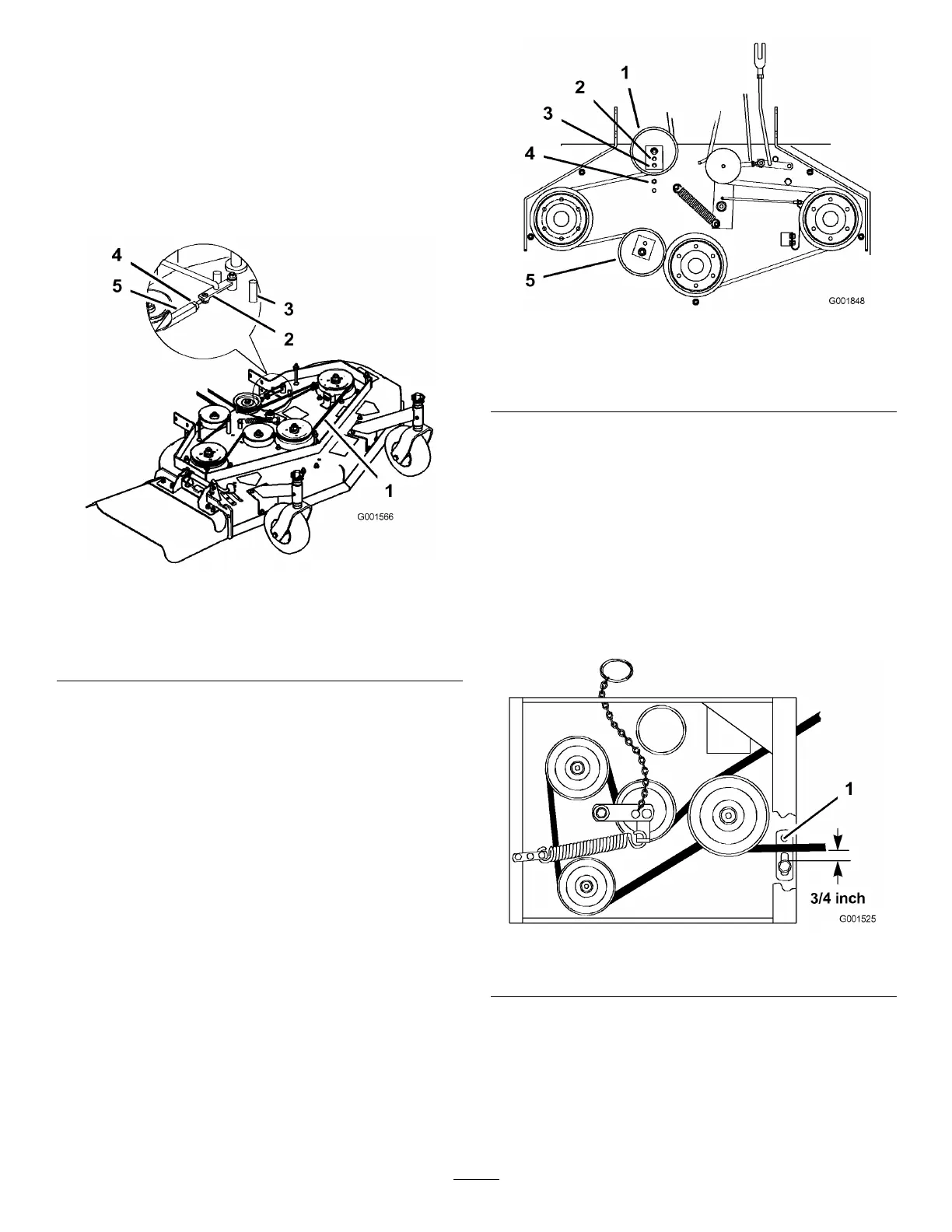
6.Ifthereisnoadjustmentleftintheturnbuckleand
thebeltisstillloose,therearidlerpulleyneedstobe
positionedtothemiddleorfronthole(Figure40).
Usetheholethatwillgivethecorrectadjustment.
7.Whentheidlerpulleyismovedthebeltguidemust
bemoved.Movethebeltguidetothefrontposition
(Figure40).
Figure40
1.Rearidlerpulley4.Beltguideinbackposition
2.Middlehole5.Frontidlerpulley
3.Fronthole
8.Checkthebeltguideundertheengineframefor
properadjustment(Figure41).
Note:Thedistancebetweenthebeltguideand
themowerbeltshouldbe3/4inch(19mm)when
youengagethemowerbelt(Figure41).Adjustthe
mowerbeltasnecessary.Thedisengagedbeltshould
notdragorfalloffthepulleywhentheguidesand
belttensionareproperlyadjusted.
9.Checkthebladebrakeadjustment;refertoAdjusting
theBladeBrake.
Figure41
1.Beltguide
AdjustingthePTOEngagement
Linkage
Important:Thebladebrakeneedstobeadjusted
whenthebelttensionorthebrakelinkageis
adjusted.
36