16
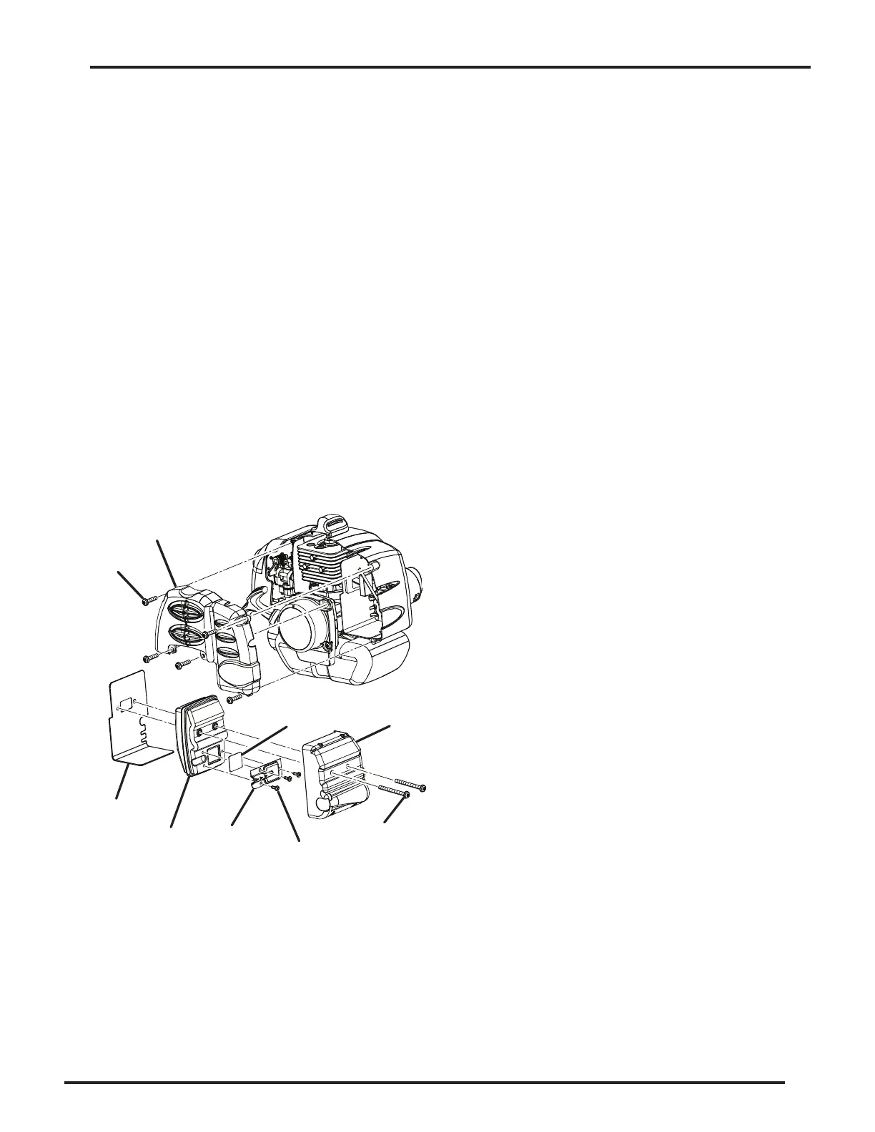
Figure 9
Maintenance
7. Rinse the air lter and let it dry completely.
8. Work two drops of oil into the air lter.
9. Replace the air lter (ts only one way).
10. Replace the air lter cover.
11. Tighten the air lter cover by turning the knob clock-
wise.
12. Replace the spark plug boot.
NOTE: Replace the air lter as indicated by the mainte-
nance schedule.
Replacing the Spark Arrestor
See Figure 9.
NOTE: Depending on the type of fuel used, the type and
amount of oil used, and/or your operating conditions, the
exhaust port and mufer may become blocked with carbon
deposits. If you notice a power loss with your gas powered
tool, you may need to remove these deposits to restore
performance. We highly recommended that only qualied
service technicians perform this service.
The spark arrester may need to be replaced after repeated
use. If replacement is necessary, use Toro part number
000998216.
Spark
Arrester
Plate
Muffler
Cover
Muffler
Gasket
Screw(s)
Screw(s)
Cover
Screw(s)
Muffler
To replace the spark arrester:
1. Remove the ve screws that hold the cover.
NOTE: Removing these screws requires the use of a
T20 and T25 torx screwdriver.
2. Remove the cover.
3. Remove the two screws holding the mufer assembly
in place.
4. Remove the mufer assembly and mufer gasket. It
may be necessary to work the mufer assembly free
from the mufer gasket.
5. Separate the mufer cover from the mufer.
6. Remove the three screws that hold the plates on the
mufer.
7. Remove the spark arrester.
8. Replace the old spark arrester with the new one.
9. Reassemble the mufer by reinstalling the plates and
tightening the three screws (torque to 18 in.lb. mini-
mum, 22 in.lb. maximum).
10. Reassemble the mufer and mufer cover and attach to
the mufer gasket with the two screws.
11. Reinsert the mufer assembly and tighten two screws
to engine (torque to 60 in.lb minimum, 80 in.lb. maxi-
mum).
12. Reinstall the cover on the tool and fasten with the ve
screws (torque to 16 in.lb. minimum, 22 in.lb. maximum).
NOTE: Do not overtighten screws.
Maintenance