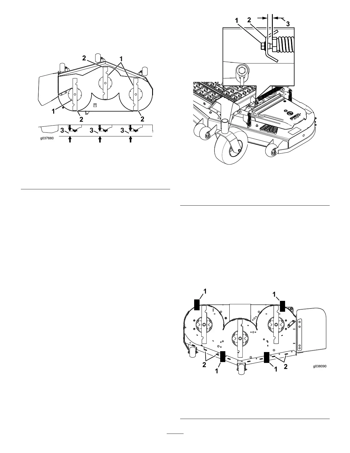
7.Checkthefront-to-rearbladelevel(Figure97).
Ensurethefrontbladetipislowerthantherear
bladetipasshownintheblockheightandrake
table.Ifadjustmentisneeded,continuewiththis
procedure.
g037880
Figure97
1.Bladesfronttorear3.Measurefromthetipofthe
bladetotheatsurface
here.
2.Bladetip
8.Settheanti-scalprollerstotopholesorremove
themcompletelyforthisadjustment.
9.Raisethedecktothetransportposition(140mm
or5-1/2inches).
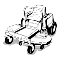
10.Slowlyloosentheadjustingscrewonthe
lift-assistspringuntilyoucanremovethescrew
(Figure98).
Note:Savethescrewforinstallation.
g334850
Figure98
1.Adjustingscrew
3.Setthegapto22to29
mm(7/8to1-1/8inches).
2.Bracket
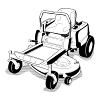
11.Place2blocks(seeBlockHeightandRake
Table)undertherearedgeofthecuttingdeck
skirt;1oneachsideofthecuttingdeck(Figure
99).
12.Settheheight-of-cutlevertothe76mm(3
inches)position;refertoAdjustingtheHeight
ofCut(page28).
13.Place2blocksundereachsideofthefrontedge
ofthedeck,butnotundertheanti-scalproller
bracketsorwelds.
g038090
Figure99
Bottomview
1.Block—73mm(2-7/8
inches)
2.Welds
68