Block Height and Rake T able
Deck
Size
Front Block Height Rake
All mower
decks
73 mm (2-7/8 inches) 4.8 to 6.4 mm (3/16 to 1/4
inch)
14. Carefully rotate the blades side to side ( Figure
86 ).
15. Lower the mower deck to the 76 mm (3 inches)
position; refer to Adjusting the Height of Cut
( page 29 ) .
16. Loosen the bolts ( Figure 90 ) on all 4 corners and
ensure that the mower deck is sitting securely
on all 4 blocks.
17. Remove any slack from the deck hangers and
make sure the deck-lift foot lever is pushed back
against the stop.
18. T ighten the 4 bolts.
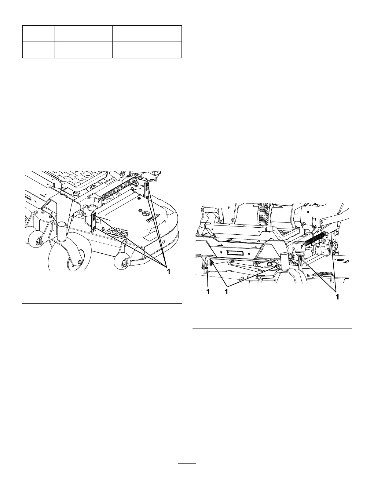
g412952
Figure 90
1. Deck-lift arm bolts
19. Ensure that the blocks t snugly under the deck
skirt and that all attachment bolts are tight
20. Continue leveling the deck by checking the
front-to-rear blade slope.
21. Check the blades for levelness and repeat deck
leveling procedure if necessary .
22. Raise the deck to the transport position (140 mm
or 5-1/2 inches).
23. Install the lift-assist spring adjusting screw
previously removed in step 10 .
24. Set the gap between the spring and the bracket
to 22 to 29 mm (7/8 to 1-1/8 inches).
Removing the Mower Deck
Before servicing or removing the mower deck, lock
out the spring-loaded deck arms.
1. Park the machine on a level surface, disengage
the blade-control switch (PT O), and engage the
parking brake.
2. Shut of f the engine, remove the key , and wait
for all moving parts to stop before leaving the
operating position.
3. Place the height-adjustment pin in the 76 mm (3
inches) cutting-height location.
4. Remove the belt covers.
5. Loosen the mower deck idler and remove the
mower belt; refer to Belt Maintenance ( page 53 ) .
6. Remove the bolts and nuts from the front of the
plate under the footrest.
7. Remove and retain the bolts and nuts on both
sides of the machine ( Figure 91 ).
8. Slide the deck out to the right side of the
machine.
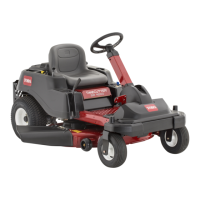
g421306
Figure 91
1. Remove the nuts and bolts here.
66