36
Checking the Hydraulic Lines
After every 100 operating hours, check hydraulic lines and
hoses for leaks, loose fittings, kinked lines, loose mounting
supports, wear, weather and chemical deterioration. Make
necessary repairs before operating.
Note: Keep areas around hydraulic system clean from grass
and debris build up.
Adjusting the Handle Neutral
Position
If motion control levers do not align, or move easily into
the console notch, adjustment is required. Adjust each
lever, spring and rod separately.
Note: Motion control levers must be installed correctly. See
Installing the Motion Control Levers in the Setup
instructions.
1. Disengage the PTO, move the motion control levers to
the neutral locked position and set the parking brake.
2. Stop the engine, remove the key, and wait for all
moving parts to stop before leaving the operating
position.
3. Tilt the seat forward.
4. Begin with either the left or right motion control lever.
5. Move lever to the neutral position but not locked
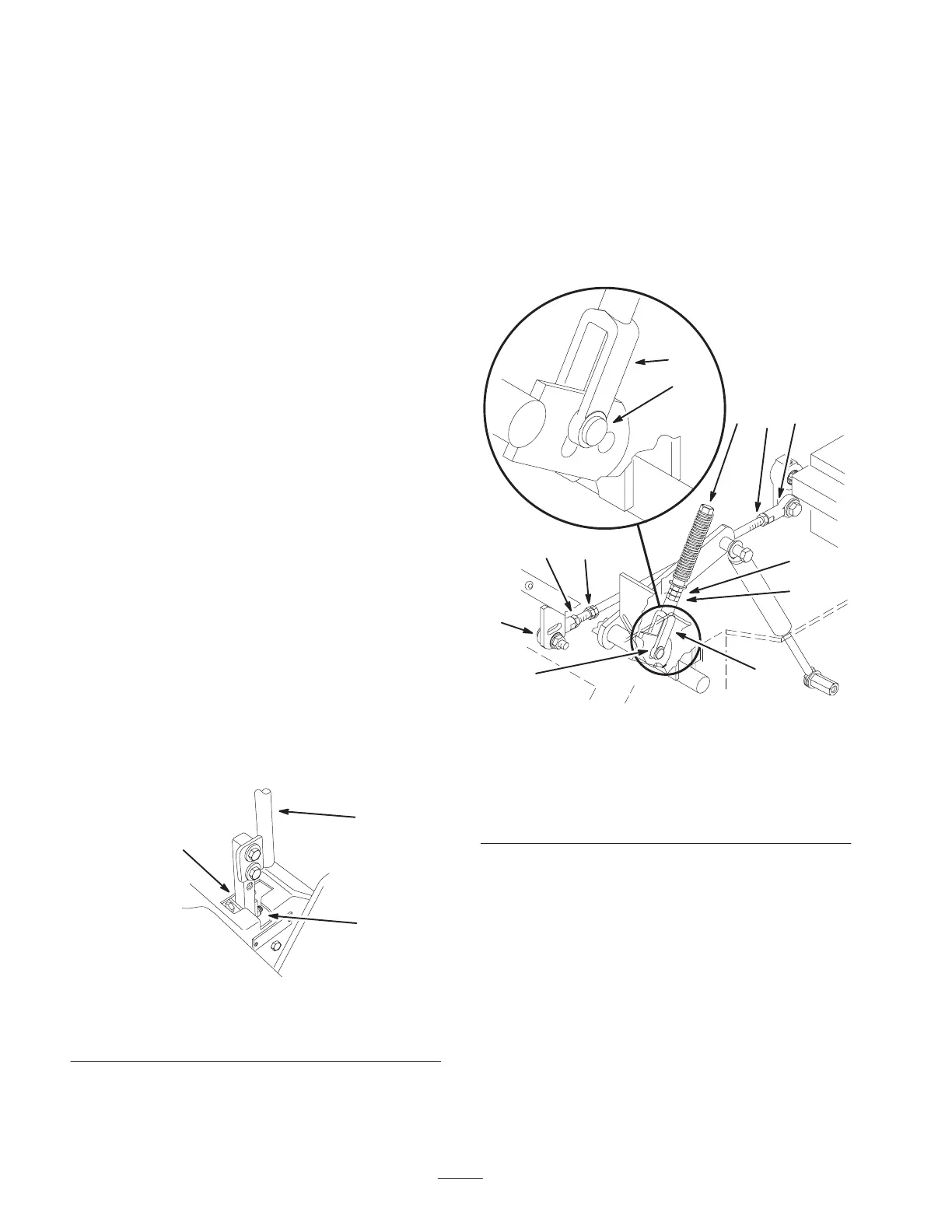
(Fig. 44).
6. Pull lever back until the clevis pin (on arm below pivot
shaft) contacts the end of the slot (just beginning to put
pressure on the spring) (Fig. 45).
7. Check where the control lever is relative to notch in
console (Fig. 44). It should be centered allowing lever
to pivot outward to the neutral lock position.
2
m–6282
1
3
Figure 44
1. Neutral locked position
2. Control lever
3. Neutral potion
8. If adjustment is needed, loosen the nut and jam nut
against the yoke (Fig. 45).
9. Apply slight rearward pressure on the motion control
lever, turn the head of the adjustment bolt in the
appropriate direction until the control lever is centered
in neutral lock position (Fig. 44).
Note: Keeping rearward pressure on the lever will keep the
pin at the end of the slot and allow the adjustment bolt to
move the lever to the appropriate position.
10. Tighten the nut and jam nut (Fig. 45).
11. Repeat on the opposite side of unit.
m–4118
1
1
2
6
4 3
2
7
9
9
8
8
Figure 45
1. Clevis pin in slot
2. Nut
3. Nut—Left hand thread
4. Adjustment bolt
5. Pump rod
6. Double nuts
7. Jam nut
8. Yoke
9. Ball joint