23
1
4
2
3
m–6883
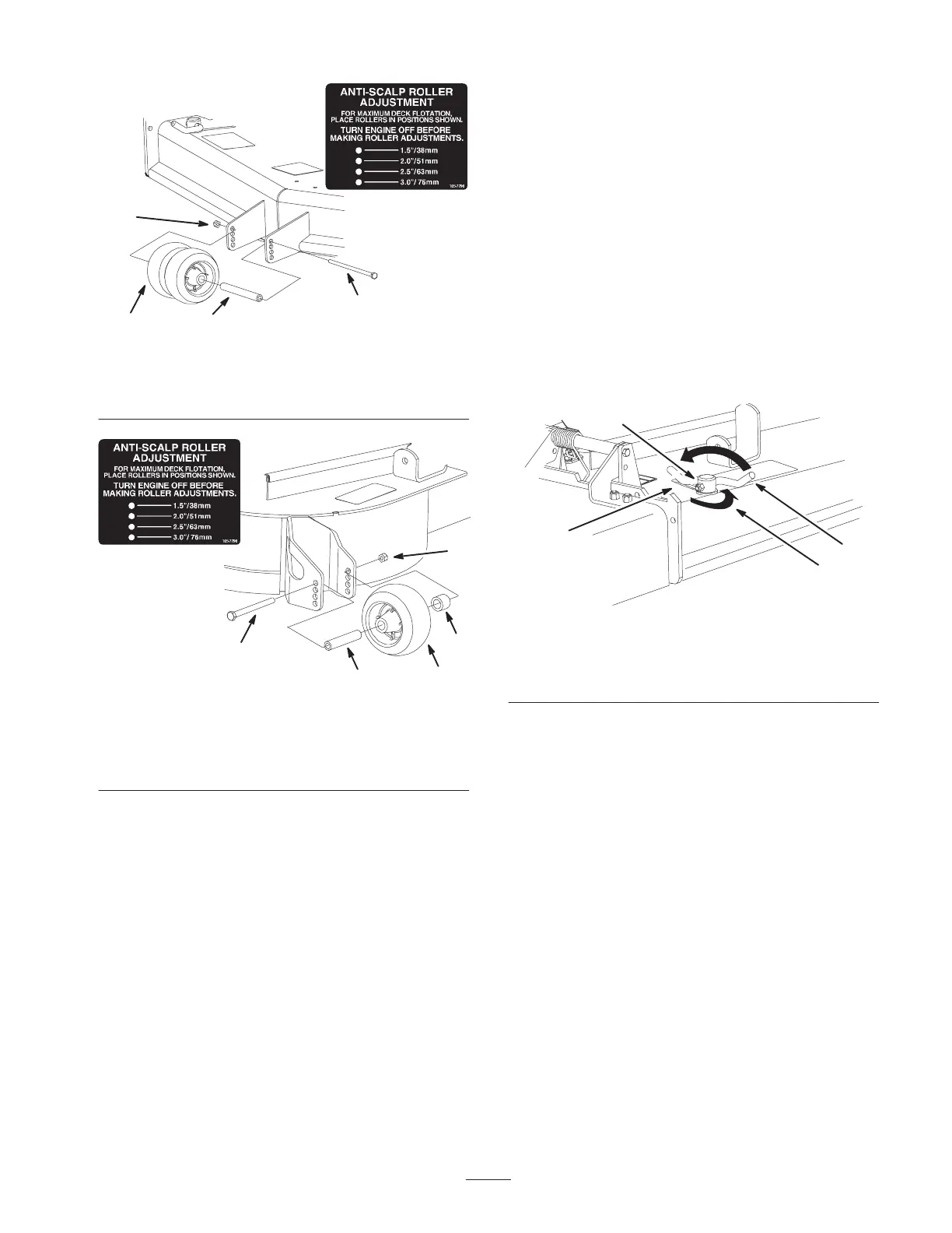
Figure 20
1. Anti–scalp roller
2. Bushing
3. Flange nut
4. Bolt
m–6844
5
3
1
2
1
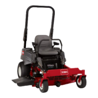
Figure 21
1. Anti–scalp roller
2. Spacer
3. Bushing
4. Flange nut
5. Bolt
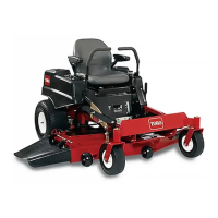
Adjusting the Flow Baffle
The mower discharge flow can be adjusted for different
types of mowing conditions. Position the cam locks and
baffle to give the best quality of cut.
1. To adjust the cam locks, swing the lever up to loosen
the cam lock (Fig. 26).
2. Adjust the baffle and cam locks in the slots to the
desired discharge flow.
3. Swing the lever back over to tighten the baffle and
cam locks.
4. If the cams do not lock the baffle into place or it is too
tight, loosen the lever and then rotate the cam lock.
Adjust the cam lock until the desired locking pressure
is achieved.
4
2
3
1
m–6884
Figure 22
1. Cam lock
2. Lever
3. Rotate cam to increase or
decrease locking pressure
4. Slot