50
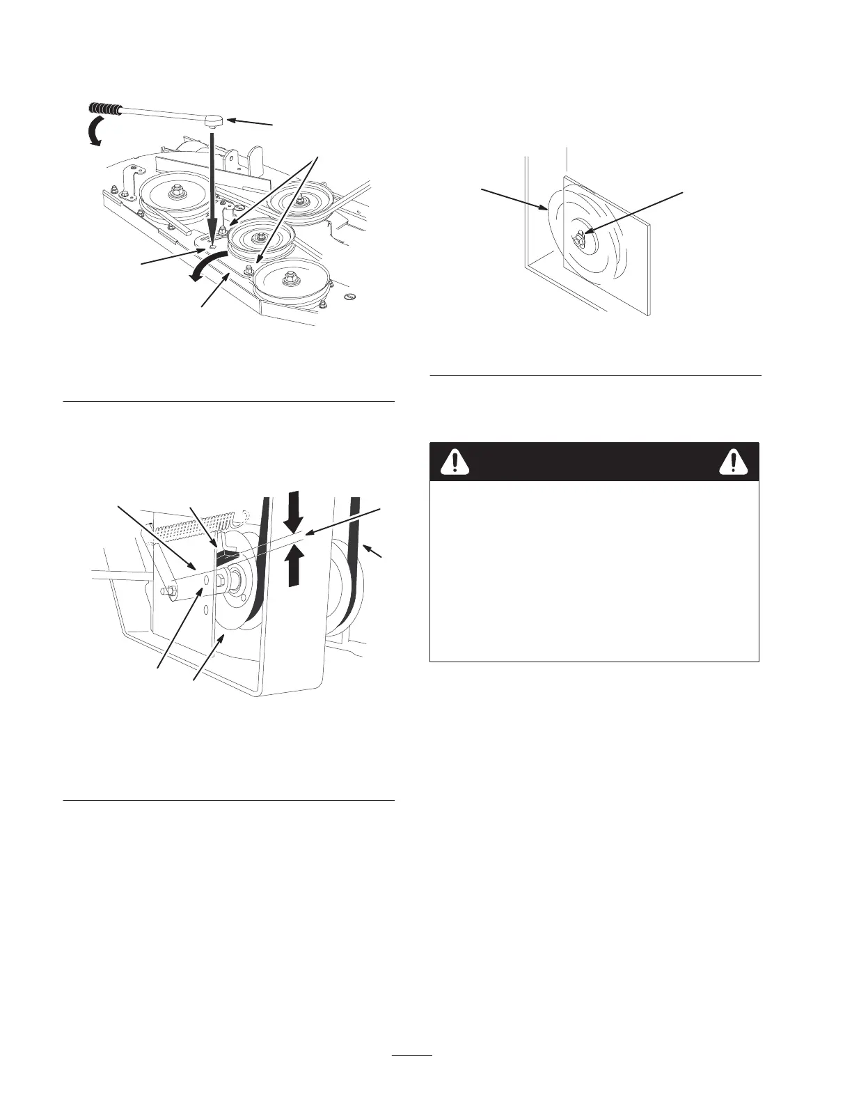
8. Tighten the idler plate bolts (Fig. 76).
2
m–6826
1
3
4
Figure 76
1. Mower idler plate
2. Square hole
3. Ratchet or breaker bar
4. Idler plate bolt
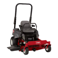
9. Check the distance from the rubber stop and the arm of
the spring loaded idler pulley when the idler plate is
tightened. It needs to be 0 to 1/4 inch (0 to 6 mm)
from the rubber stop (Fig. 77).
m–6825 1
2
3
5
4
6
Figure 77
1. Spring loaded idler pulley
2. Top alignment hole
3. 0 to 1/4 inch gap
(0 to 6 mm)
4. Idler pulley arm
5. Belt
6. Rubber bumper
10. Adjust the belt tension and the idler plate, if necessary,
and tighten all hardware securely (Fig. 76).
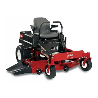
11. If the mower idler plate contacts the end of the
adjustment slot and more belt tension is required, a
small change to the right side fixed idler can create
more belt tension adjustment (Fig. 78).
m–3746
12
Figure 78
1. Fixed Idler 2. Adjustment slot
Replacing the Grass Deflector
An uncovered discharge opening could allow the
lawn mower to throw objects in the operator’s or
bystander’s direction and result in serious injury.
Also, contact with the blade could occur.
• Never operate the lawn mower unless you
install a cover plate, a mulch plate, or a grass
chute and catcher.
• Make sure the grass deflector is in the
down position.
Warning
1. Remove the locknut, bolt, spring and spacer holding
the deflector to the pivot brackets (Fig. 79). Remove
damaged or worn grass deflector.
2. Place spacer and spring onto grass deflector. Place the
L end of spring behind deck edge.
Note: Make sure the L end of spring is installed behind
deck edge before installing the bolt as shown in figure 79.
3. Install bolt and nut. Place J hook end of spring around
grass deflector (Fig. 79).