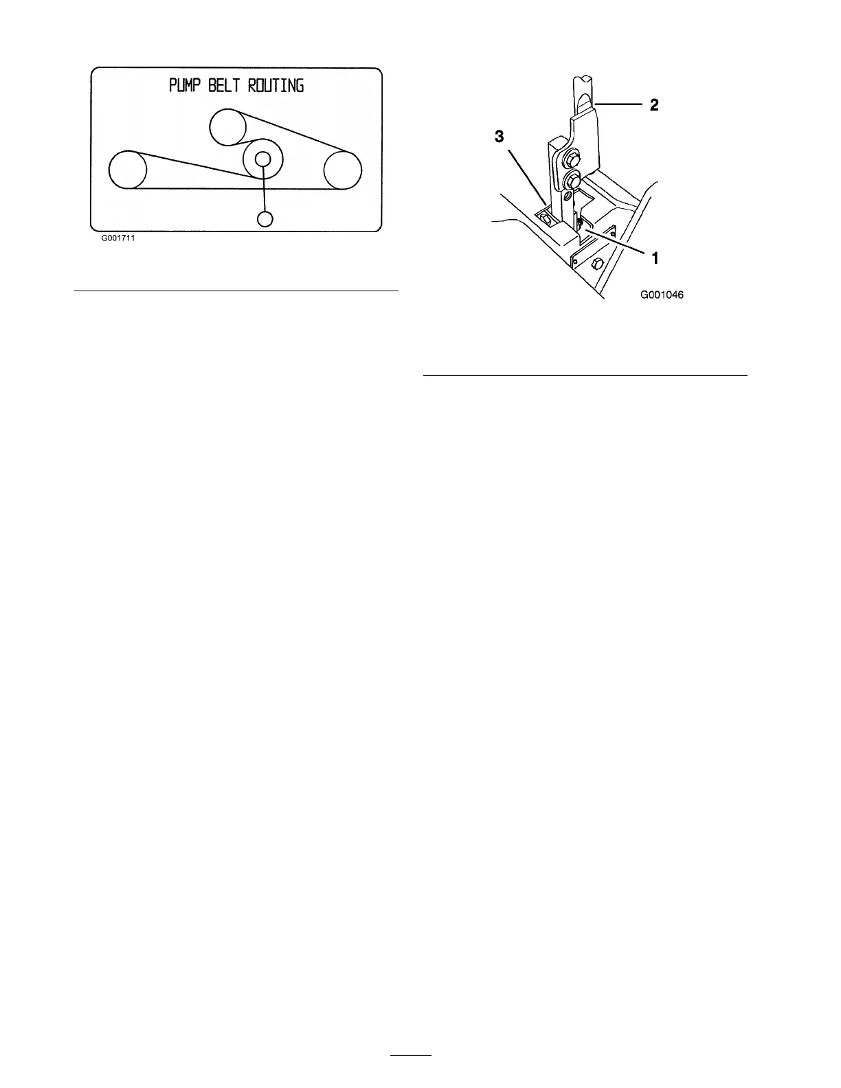
Figure 49
2. Install new belt around engine and h y dro pump
pulleys ( Figure 49 ).
3. Pull spring loaded idler do wn and align belo w
traction belt. R elease the pressure on the
spring loaded idler ( Figure 49 ).
Controls System
Maintenance
Adjusting the Control
Handle Neutral Position
If motion control lev ers do not align, or mo v e
easily into the console notc h, adjustment is
required. Adjust eac h lev er , spring and rod
se parately .
Note: Motion control lev ers m ust be installed
cor rectly . See Installing the Motion Control Lev ers
in the set up instr uctions .
1. Diseng ag e the PTO , mo v e the motion control
lev ers to the neutral loc k ed position and set
the parking brak e .
2. Stop the engine , remo v e the k ey , and w ait for
all mo ving par ts to stop before lea ving the
operating position.
3. Unlatc h the seat and tilt the seat forw ard.
4. Begin with either the left or right motion
control lev er .
5. Mo v e the lev er to the neutral position but not
loc k ed ( Figure 50 ).
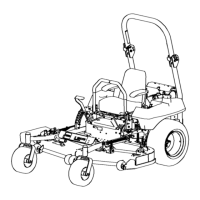
Figure 50
1. Neutral locked position 3. Neutral position
2. Control lever
6. Pull the lev er bac k until the clevis pin (on ar m
belo w pi v ot shaft) contacts the end of the slot
(just beginning to put pressure on the spring)
( Figure 50 ).
7. Chec k where the control lev er is relati v e to
notc h in console ( Figure 50 ). It should be
centered allo wing lev er to pi v ot outw ard to the
neutral loc k position.
8. If adjustment is needed, loosen the n ut and
jam n ut ag ainst the y ok e ( Figure 51 ).
9. Apply slight rearw ard pressure on the motion
control lev er , tur n the head of the adjustment
bolt in the appropriate direction until the
control lev er is centered in the neutral loc k
position ( Figure 51 ).
Note: K ee ping rearw ard pressure on the
lev er will k ee p the pin at the end of the slot and
allo w the adjustment bolt to mo v e the lev er to
the appropriate position.
10. Tighten the n ut and jam n ut ( Figure 51 ).
11. R e peat for the opposite side of the mac hine .
40