Product Overview
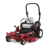
Figure 3
1. Rollbar 6. Side discharge chute
2. Fuel cap (both sides)
7. Front caster wheel
3. Seat belt 8. Controls
4. Motion control lever 9. Mower deck
5. Height-of-cut lever 10. Parking brake lever
Controls
Become familiar with all the controls before y ou
star t the engine and operate the mac hine ( Figure 3
and Figure 4 ).
Figure 4
1. Ignition switch 6. PTO Switch
2. Motion control lever 7. Height-of-cut lever
3. Brake lever
8. Fuel cap (both sides)
4. Throttle control
9. Hour meter
5. Choke
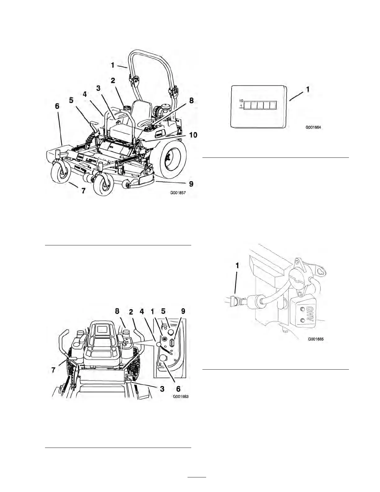
Using the Hour Meter
T he hour meter ( Figure 5 ) records the n umber
of hours the engine has operated. It operates
when the engine is r unning . Use these times for
sc heduling regular maintenance .
Figure 5
1. Hour meter
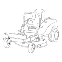
Using the Fuel Shutoff Valve
T he mac hine has 2 fuel tanks , one on the left side
and the other on the right side . Eac h tank connects
to a c hec k v alv e and then to a tee . F rom there a
common fuel line leads to the engine ( Figure 6 ).
Close the fuel shutoff v alv e before transpor ting
or storing the mac hine .
Figure 6
1. Fuel shutoff valve
13