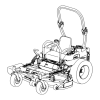
4.Positionthemowerdeckinthetransport-lock
position.
5.Carefullyrotatethebladesfromsidetoside.
6.Measurebetweenthebladetipandtheat
surface(Figure80).Ifbothmeasurementsare
notwithin5mm(3/16inch),adjusttheleveling;
continuewiththisprocedure.
g037879
Figure80
1.Bladessidetoside
3.Measurefromthetipofthe
bladetotheatsurface
here.
2.Bladetip
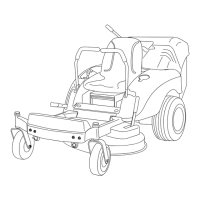
7.Checkthefront-to-rearbladelevel(Figure81).
Ensurethefrontbladetipislowerthantherear
bladetipasshownintheblockheightandrake
table.Ifadjustmentisneeded,continuewiththis
procedure.
g037880
Figure81
1.Bladesfronttorear3.Measurefromthetipofthe
bladetotheatsurface
here.
2.Bladetip
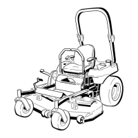
8.Settheanti-scalprollerstotopholesorremove
themcompletelyforthisadjustment.
9.For60-inchmowerdecksonly:
A.Raisethedecktothetransportposition
(12.7cmor5inches).
B.Slowlyloosentheadjustingscrewonthe
lift-assistspringuntilyoucanremovethe
screw(Figure82).
Note:Savethescrewforinstallation.
g035850
Figure82
1.Adjustingscrew
3.Setthegapto22to29
mm(7/8to1-1/8inch).
2.Bracket
10.Place2blocks(seeBlockHeightandRake
Table)undertherearedgeofthecuttingdeck
skirt;1oneachsideofthecuttingdeck(Figure
83).
11.Settheheight-of-cutlevertothe3inch(76mm)
position.
12.Place2blocksundereachsideofthefrontedge
ofthedeck,butnotundertheanti-scalproller
bracketsorwelds.
63