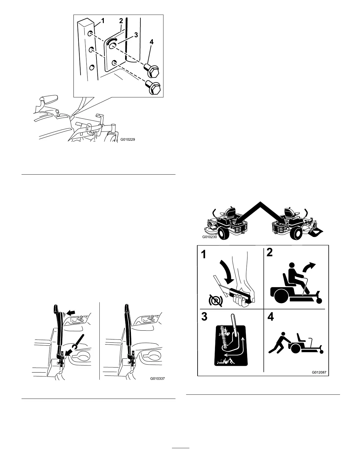
Figure29
1.Controlarmshaft3.Slotted,upperhole
2.Controllever
4.Bolt
3.Repeattheadjustmentfortheoppositecontrol
lever.
AdjustingtheTilt
Themotioncontrolleverscanbetiltedforeoraftfor
maximumoperatorcomfort.
1.Loosentheupperboltholdingthecontrolleverto
thecontrolarmshaft.
2.Loosenthelowerboltjustenoughtopivotthe
controlleverforeoraft(Figure29).Tightenboth
boltstosecurethecontrolinthenewposition.
3.Repeattheadjustmentfortheoppositecontrol
lever.
Figure30
PushingtheMachinebyHand
Important:Alwayspushthemachinebyhand.
Nevertowthemachinebecausedamagemay
occur.
ToPushtheMachine
1.Parkthemachineonalevelsurfaceanddisengage
thebladecontrolswitch.
2.Movethemotioncontrolleversoutwardtoneutral
lockposition,stoptheengine,removethekey,and
waitforallmovingpartstostopbeforeleavingthe
operatingposition.Makesuretheparkingbrakeis
disengaged.
3.Locatethebypassleversattherearofthemachine,
ontheleftandrightsideoftheframe.
4.Movethebypassleversrearwardandthendown
tolocktheminplaceasshownin
Figure31to
disengagethewheelmotors.Repeatthisoneach
sideofthemachine.
Themachineisnowabletobepushedbyhand.
Figure31
ToOperatetheMachine
Movethebypasstothepositionfordrivingthemachine
(Figure31)toengagethewheelmotors.
24