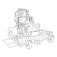
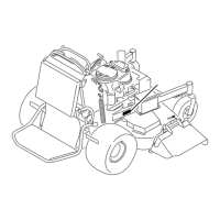
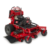
Figure63
1.Hydraulicpumps
4.Clutchretainer
2.Idlerpulley
5.Clutchwireconnector
3.Clutchpulley
6.Pumpdrivebelt
7.Unhooktheidlerspringfromtheframe(Figure63).
8.Installthenewbeltaroundclutchandthetwopump
pulleys.
9.Installtheidlerspringbetweenidlerarmandframe
bracket(Figure63).
10.Installtheclutchretainertotheenginedeck
(Figure63).
11.Connecttheclutchwireconnectortothewire
harness.
12.Lowerthemachinetotheoperatingposition.
RefertoPre-Maintenanceatthebeginningofthe
MaintenanceSection.
13.Installthemowerdeckbelt.
ControlsSystem
Maintenance
AdjustingtheMotionControl
HandlePositions
AdjustingtheRightSideMotionControl
Lever
Ifthemotioncontrolleversdonotalignhorizontally,
adjusttherightsidemotioncontrollever.
Note:Adjustthehorizontalalignmentbeforethefront
tobackalignment.
1.DisengagethePTO,movetherightsidemotion
controllevertotheneutralpositionandsetthe
parkingbrake.
2.Stoptheengine,removethekey,andwaitforall
movingpartstostopbeforeleavingtheoperating
position.
3.Pushtherightmotioncontrolleverdownoutof
lockedneutralposition(Figure64).
4.Checkifitalignshorizontallywiththeleftmotion
controllever(Figure64).
Figure64
1.Leftmotioncontrollever3.Checkthehorizontal
alignmenthere
2.Rightmotioncontrollever
inneutrallockedposition
4.Rightmotioncontrollever
5.Toadjusttherightmotioncontrolleverhorizontally,
thecamneedstobeadjusted.
6.Removethecushionfromtherearofthemachine.
7.Loosenthenutandboltholdingthecam(Figure65).
8.Adjustthecamuntilitalignswiththeleftmotion
controlleverandtightenthenutandboltforthe
cam.
44
 Loading...
